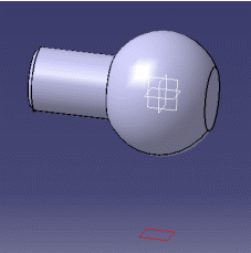
-
Select Plane1 and go into Sketcher workbench.
-
Click 3D Silhouette Edges
 from the Operation toolbar (3D Geometry
sub-toolbar).


-
Select the canonical surface.
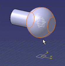
These silhouette edges are yellow if they are associative with the 3D.
You cannot move or modify them but you can delete one of them which means deleting one trace independently from the other.
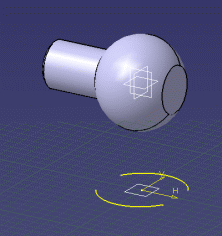
and set it into the Construction mode:
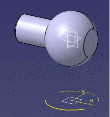
You can create geometry and constraints using this intersection:
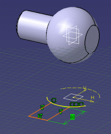
using the geometry:
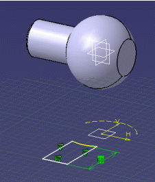
- Silhouette edges are associative except in the case of a multiple distinct marks.
- A mark composed of several associated elements is managed as a single curve (you can constrain it).
- If you apply the Parents/Children... command to a sketch containing a 3D silhouette, the Parents command shows the last solid feature that modified the silhouette. To see an example of this, refer to Parents/Children paragraph of Projecting 3D Elements onto the Sketch Plane.
![]()