-
Multi-select the edges you wish to project onto the sketch plane.
The edges are projected onto the sketch plane. These projections are yellow. You cannot move these elements. To move them, first use the Isolate command.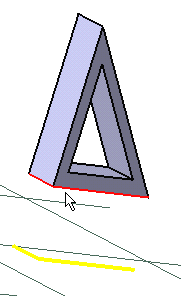
-
You can apply the Relimitation
 ,
Corner
 and Chamfer
 commands on projections.
 -
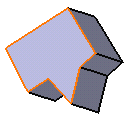
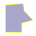
If you select a face, its edges are projected.
Parents/Children
If you apply the Parents/Children... command to a sketch
containing a projected edge obtained after selecting a face or an edge, the
Parents command shows the last solid feature that modified the projected
geometry.
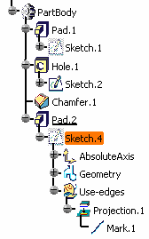
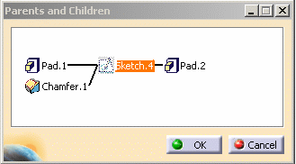
In the example below, one of Pad1's edge has been projected and used in
Sketch4. The capability shows a parent relationship with Pad1 but also with
Chamfer1 that is the last feature in the part body.
|
- A canonicity detection is performed on projected curve according to
the application tolerance, in other words the application tries to
recognize sketcher elements like line or conic curves.
Due to the canonicity approximation changes may occur in resulting projected curve types. - If no canonicity has been detected the curve is projected as is.
- Projected elements are associative except in the case of multiple distinct marks.
- A mark composed of several associated elements is managed as a single curve (you can constraint it).
- In general, we recommend not to create projections from wireframe elements which lie on a plane orthogonal to the sketch. As a matter of fact, the orientation of the result of these projections in the sketch plane is not stable.
- If you isolate a composite mark, as many simple geometry elements as the mark was containing are created, associativity will not be available anymore.
- A multi-domain face projection does not create a single composite mark (in this case each edge is projected).
