- Copying/pasting elements with H and V constraints on their absolute axis
- Copying/pasting projected or intersected elements
- Copying Sketches
For general information on copy/paste, see the Infrastructure User's Guide.
Copying/pasting elements with H and V constraints on their absolute axis
This task shows you how to copy/paste elements along with the horizontal and vertical constraints on their absolute axis.
-
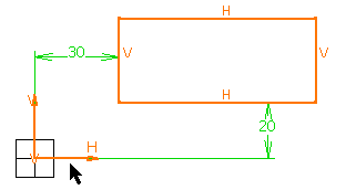
To duplicate the rectangle and its H and V directions: multi-select the rectangle and its origin, and copy the selected elements

-
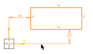
To duplicate the rectangle, its H and V directions, and the distance constraints which exist between the rectangle and its origin: multi-select the rectangle and the distance constraints (do not select the origin), and copy the selected elements.

In other words, if you want to copy an element along with its H and V direction while keeping the constraints which exist between the copied element and its origin, you do not need to, and you should not, select the origin. Selecting the constraints is enough. If you select the origin, the constraints will not be kept.
-
Paste these elements.
The elements are pasted over the elements you copied. You can move the pasted elements (if you want to view them, for example).
Copying/pasting projected or intersected elements
This task shows how sketched elements that were created via projection or intersection behave when copying/pasting them.
-
Copy the projected or the intersected element, using the method described above.
-
Paste this element.
External references are deleted:
-
Constraints on external geometry are deleted.
-
Projections/Intersections are isolated: each trace is replaced with an equivalent geometrical element.
-
You cannot project or intersect the pasted element.
-
The pasted element is not associative.
Copying Sketches
This task shows how pasted sketches behave.
-
Create a sketch then enter Part Design workbench.

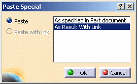
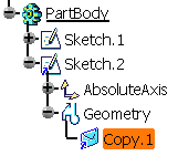
The sketch is pasted. You can observe a blue symbol added to the image of the sketch in the specification tree, meaning that associativity is maintained between the reference geometry and the copy.

-
Use this copied sketch to create a pad.
-
Just edit the reference sketch the way you want: for example, change the shape. The pad reflects the change.
In the specification tree, sketches copied and pasted in documents different from the documents in which they were created are identified by a green point in target documents:
![]()
The green point is turned into a red cross when the copied sketch needs synchronizing with its reference:
![]()