-
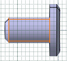
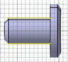
Select the face of interest.

- You can apply the Relimitation
 ,
Corner
 and Chamfer
 commands on projections.
 - If you select a face, its edges are projected.
- A canonicity detection is performed on projected curve according to
the application tolerance, in other words the application tries to
recognize sketcher elements like line or conic curves.
Due to the canonicity approximation changes may occur in resulting projected curve types. - If no canonicity has been detected the curve is projected as is.
- Intersected element are associative apart in the case of a multiple distinct marks.
- A mark composed of several associated elements is managed as a single curve (you can constraint it).
- If you apply the Parents/Children... command to a sketch containing an intersection obtained after selecting a face or an edge, the Parents command shows the last solid feature that modified the intersection geometry. To see an example of this, refer to Parents/Children paragraph of Projecting 3D Elements onto the Sketch Plane.
- If you isolate a composite mark, as many simple geometry elements as the mark was containing are created, associativity will not be available anymore.
- If the intersected geometry is a plane face and there is no intersection between this face and the sketcher plane, the resulting intersection is an infinite line.
