Creating Constraints Between 2D and Generated Elements

This task shows you how to create associative constraints between 2D elements and generated elements (Generative Drafting workbench).
Open the GenDrafting_part_Broken_View.CATDrawing document. Make sure both the Show Constraints and the Create Detected Constraints icons are active in the Tools toolbar.


  • It is impossible to create constraints between 2D and generated elements via the Constraint Definition dialog box.
  • In the Constraint Definition dialog box, you can only create constraints between similar elements (either between 2D elements, or between generated elements, but not between a mix of these).
  1. Create a line in the opened drawing.

  2. Select this line.

  3. Click the Geometrical Constraint icon   from the Geometry Modification toolbar.
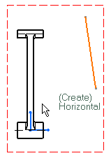
 

  The software offers to create the most logical constraint (if you want to apply this constraint, click in the drawing to validate).
 
  Select a generated edge from the drawing you have opened.
 
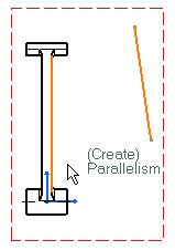
  The software offers to create a parallelism constraint by default. If you want to apply this constraint, click in the drawing, otherwise...
  1. ...right-click and select Perpendicularity in the contextual menu.


  A constraint is created between the generated element and the 2D element.


You can delete this constraint by right-clicking the created constraint and selecting Delete in the contextual menu.
No constraints can be created  between 2D and generated elements whenever:
  • The front view of the 3D revolution surface is not perfectly positioned. See example here below:
     
  • The 3D surface is not a regular one. See example here below.