-
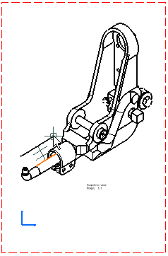
In the Drawing window, click Quick Detail View Profile
 in the Views toolbar (Details sub-toolbar).
 To create a detail view using a circle as callout, click Quick Detail View
") .
. -
Select the points required for sketching a polygon.
If you are creating a detail view using a circle as callout, click the callout center.
-
Double click to end the cutting profile creation. Note that if you do not close the profile, it will be closed automatically.
If you are creating a detail view using a circle as callout, drag to select the callout radius and click a point to end the selection.
-
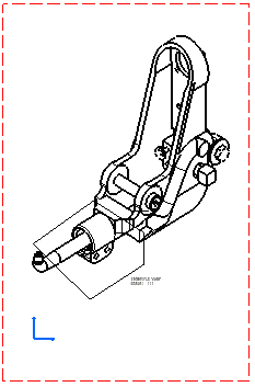
Click to generate the quick detail view.
Unlike a detail view
") ,
the profile is entirely closed. You can modify the detail view profile
through the Properties dialog box.
,
the profile is entirely closed. You can modify the detail view profile
through the Properties dialog box.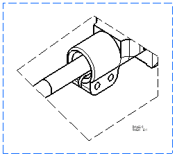
- The default scale is 2 (twice the scale of the active view). To modify this scale, right-click the detail view, select Properties and then the View tab. Enter the desired Parameters Scale and then click OK.
- You can insert Bill of Material information into the active view.
- You can assign a line type to the view to be generated. To do this, go to Tools > Options > Mechanical Design > Drafting > View tab, click the Configure button next to View Linetype and select the desired option from the dialog box.
![]()