Note that the sag value cannot be modified for objects composed of multiple shapes.
Be sure you work in visualization mode, with the Cache system on. To activate the cache system, see Activating the Cache.
-
Double-click the Interference Results.1 in the specification tree.
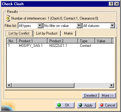
The Check Clash dialog box appears.
There is a contact detected between MODIFY_SAG.1 and NOZZLE1.1.

You are now going to modify the sag value of the two components
involved in the clash detection to obtain a finer result. When done, you
will run the clash detection again.
-
Select the components you need in the specification tree (e.g. NOZZLE1.1, NOZZLE2.1, ATOMIZER.1 and MODIFY_SAG.1).

-
Select the Tools -> Modify Sag command.
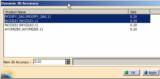
The Dynamic 3D Accuracy dialog box appears. The sag field provides information on the current sag applied to the selected component.
Note that all the documents in the 3D Accuracy dialog box are selected and that the Apply button is grayed out since no modification has been proposed.
Note that 0.2 is the default sag value (see Tools -> Options-> General -> Display -> Performances -> 3D accuracy -> fixed).
The sag corresponds to the fixed sag value for calculating tessellation on objects (3D fixed accuracy) set in the Performances tab of Tools -> Options -> General -> Display. By default, this value is set to 0.2 mm. The sag value set in this tab is offset from the skin inwards on both selection 1 and selection 2.
Managing 3D Accuracy allows you to modify sag value depending on the tasks performed (clash detection, review).
The 3D Accuracy controls the tessellation of surfaces (the surfaces of your geometry are built using a mesh of polygons). You have two choices in the Tools -> Options-> General -> Display -> Performances dialog box:
- fixed sag value (values between 0 and 1) for calculating tessellation on all objects, which does not vary with object size
- proportional sag value (values between 0 and 10) for calculating tessellation on all objects, which does vary with object size
A low value (close to 0) means that a very fine mesh is used to render surfaces, but the drawback is that geometry will be redrawn more slowly when using the viewing tools
A high value (close to 1 for a fixed sag value, close to 10 for a proportional sag value) means that a very coarse mesh is used, but the advantage is that geometry will be redrawn much faster.
Note the following general behavior:
- When the Dynamic 3D Accuracy dialog box is opened, all the documents are selected. You can select those documents in the list for which you wish to modify the SAG value.
- If no document is selected or the selected ones already have the specified New 3D Accuracy value, the Apply button is not grayed out.
- When you click the Apply button, the selected documents are re-tessellated with the specified New 3D Accuracy value. The values in the SAG column are updated accordingly.
- The Apply command can be used multiple times in order to perform multiple re-tessellations with the 3D Accuracy values of your choice and without exiting the dialog box.
- When you click the Close button, the Modify SAG panel is closed. Note, however, that this does not have the effect of an "undo"; the documents are not restored with the sag value that they had before you launched the Modify SAG command.
- When you click the OK button, the selected documents are re-tessellated with the specified New 3D Accuracy value and the Dynamic 3D Accuracy dialog box is closed.
- When the New 3D Accuracy is modified by entering a value with the keyboard (instead of using the spinner) the Apply button availability is not automatically updated. You must validate the entered value by typing Enter and then the Apply button will be available.
-
Select MODIFY_SAG.1 and NOZZLE1.1 and modify the New 3D Accuracy value.

Note that the Apply button is no longer grayed out.
-
Click the Apply button.

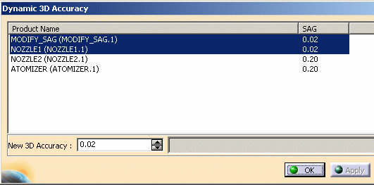
The progress bar is activated during the re-tessellation process. The selected documents are re-tessellated with a SAG value of 0.02 and remain selected in the dialog box. The Apply button is now grayed out.
You can repeat steps 4 and 5 as many times as you wish.
-
Click the Close button to exit the dialog box.
The resulting mesh is now much finer:

-
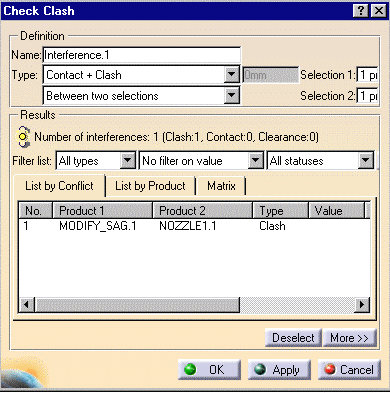
Double-click Interference.1 in the specification tree and click Apply.
The calculation is launched. The new sag value has been taken into account. The contact has become a clash.
![]()
