-
Click No Splice Zones
 in the Splice Zones toolbar.
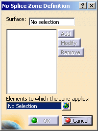
The No Splice Zones dialog box is displayed.

-
Select the surface on which the zones will be created.
Its name is displayed in the dialog box. -
The button Add is now available.
Click Add.
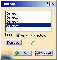
The Contour dialog box is displayed.
Select the curves that will define the No Splice Zone.
The curves must form a closed contour. They are displayed in the dialog box.
Use Add and Remove to add or remove a curve
Use Insert After, Before and Remove to modify the order of the curves as well as the contour.

Click OK to revert to the main dialog box.
-
Select the Elements to which the zones apply. We have selected the Stacking.

- Multi-selection is available.
- The elements can be a stacking, plies groups, sequences, plies.
-
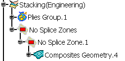
Click OK. A No Splice Zones group is created under the Stacking, if it does not already exist, and the No Splice Zone is created in that group.

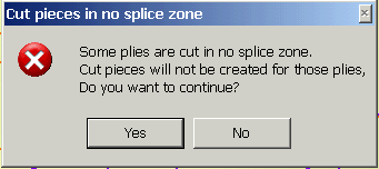
- If you try to create 3D Multisplice, a message is displayed

- If you click Yes, the list of the splicing curves that intersect the No Splice Zones is displayed and you are invited to check your design.
- No Splice Zones are taken into account by the
Skin Swapping command if you select
the Stacking node.
If you applied the Skin Swapping was applied to elements under the staking, you can generate a Skin Swapping feature for the No Splice Zones by selecting either a zone or its group. In this case a Skin Swapping feature will be added at the end of the Composites Geometry of the corresponding elements.
![]()