![]()
- Skin swapping can be performed only on tangency continuous shells.
- When a Swapping feature already exists, you can not create a second one, but you can edit it if modifications are required.
-
Click Swapping
 .
. -
Select the feature where you want to insert the swapping in the specification tree.
It can be a ply, a sequence, a group of plies, cut-pieces or a stacking.
In our scenario, we selected the Stacking (manufacturing).
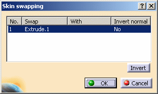
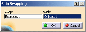
The Skin swapping dialog box is displayed.
The engineering surface to be swapped is already selected in the Swap frame (Extrude.1).
-
Swap this surface With the manufacturing surface (Offset1).
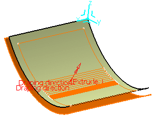
The draping direction is displayed in the 3D geometry.
You can click Invert to reverse the draping direction and be consistent with the direction defined in the engineering plies.
-
Click OK in the Skin swapping dialog box.
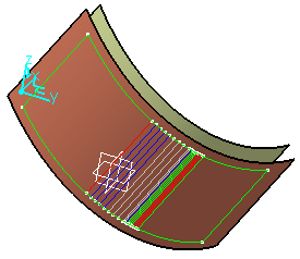
The engineering geometry is transferred onto the manufacturing surface.
It is put in the No show space on the engineering surface.
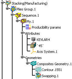
In the specification tree, the Swapping feature (identified as Swapping.xxx) is displayed under each ply.
-
Double-click Swapping.1 element in the specification tree.
-
The Skin Swapping dialog box is displayed.
-
Select the new manufacturing surface.
-
Click OK to perform the modification.
-
Only the ply referencing the feature is modified.
-
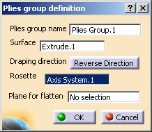
Double-click the Plies Group.1 feature in the specification tree.
-
The Plies group definition dialog box is displayed.
-
Click Change and select the new manufacturing surface.
-
Click OK to perform the modification.

If you applied the Skin Swapping was applied to elements under the staking, you can generate a Skin Swapping feature for the Butt Splice Zones by selecting either a zone or its group. In this case a Skin Swapping feature will be added at the end of the Composites Geometry of the corresponding elements.
![]()