-
Create plies from zones.
Make sure you select both Zone Group.1 and Zone Group.2. The plies are created under Plies Group.1. -
Create a plies group.
-
Click Ply
 and select Plies Group.2 you just created.
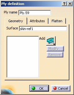
The Ply Definition dialog box is displayed.
The Surface field is automatically populated since the ply inherits the plies group properties.
-
Click Add to select a contour via the Contour dialog box.
-
Select four curves in the geometry so as to create a closed contour.
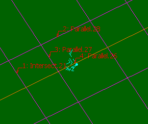
In the example above, Plies Group.1 has been put in no show to display the contour better.
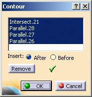
The curves composing the contour are displayed in the Contour dialog box.
Should you need to create the curves for the ply contour, right-click in the field and create the element you need.
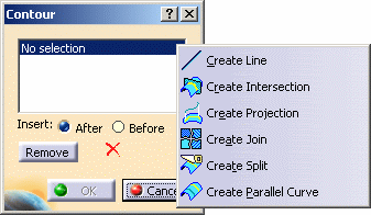
Refer to Generative Shape Design & Optimizer User's Guide for more information. -
Click OK to add the features composing the ply geometry.
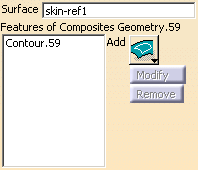
- Modify lets you manually modify the contour geometry via the Contour dialog box: select other curves to form the closed contour.
- Remove lets you remove a contour or a curve composing the contour: simply select the contour or curve and click Remove.
-
In the Attributes tab, define the :
- Material using the combo
- Direction using the combo
- Rosette either in the 3D geometry or in the specification tree
The list of Materials and the Direction attributes were defined in the Composites Parameters.
-
Click OK to create the ply.
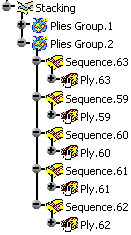
The Stacking node includes the plies groups, the set of sequences (order), and for each sequence, the set of plies (containing the geometry)
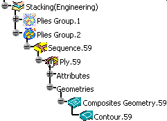
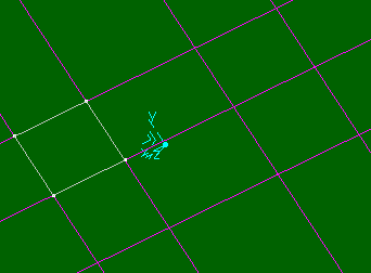
-
Create three more plies, selecting the pink curves as contour on the geometry.
Here is the result of the plies creation.
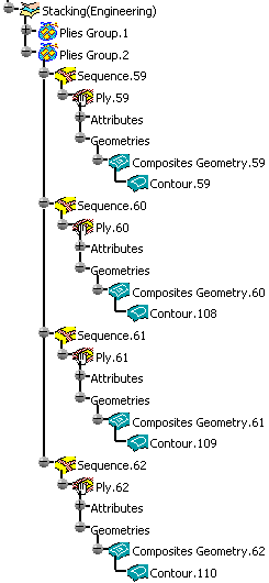
Plies are displayed in the 3D geometry according to a color code depending on their orientation.
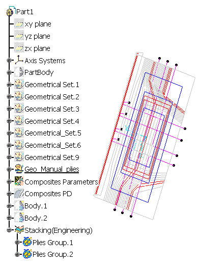
-
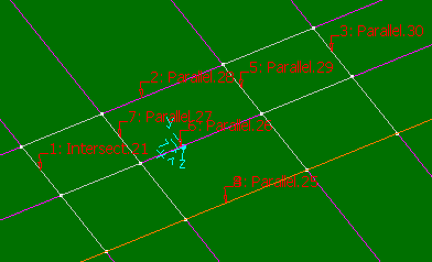
You are now going to create a ply selecting twice the same curve in order to create the ply shown below.
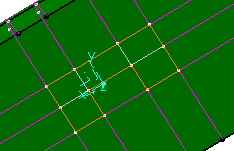
Click Ply and select Plies Group.2.
 -
Click Add to select a contour via the Contour dialog box.
-
Select the curves in the geometry so as to create a closed contour, starting with Intersect.21.
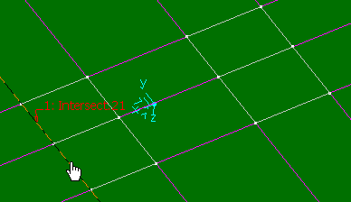
-
Select Parallel.25 to close the ply contour.
This curve has thus to be selected twice.
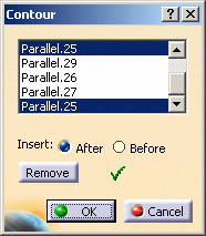
-
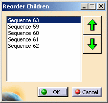
Right-click Plies Group.2 and select Plies Group.2 object, then Reorder children.
The sequence of plies are displayed in the Reorder Children dialog box. -
Select Sequence.63 for instance and use the up and down arrows to modify its place in the stacking.
-
Click OK.
The specification tree is modified accordingly.
-
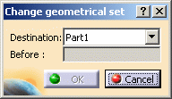
Right-click Ply.59 and select Ply.59 object, then Change Geometrical Set.
The following dialog box is displayed, in which all the elements of the specification tree are available.
-
Select the sequence you would like to move Ply.59 to.
In our example we selected Sequence.62. -
Click OK.
The specification tree is modified accordingly.
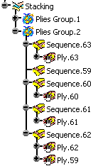
- Note that Change Geometrical Set command enables you to move a ply from one sequence to another, whereas performing a copy/paste of a ply in a sequence creates a new ply.
- Moving a ply using the Change Geometrical Set command is taken into account when synchronizing a manufacturing document.
- the ply is highlighted in the model;
- information is displayed in the status bar.
- select it in the model;
- right-click it, then select Center graph.
- To edit an existing ply, simply double-click it in the specification tree. The Ply Definition dialog box opens and you are able to modify its contours and attributes.
![]()