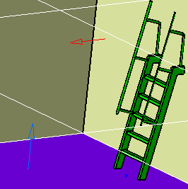
- After you select the ladder in the Catalog Browser, select the
placement boundary.
Since the connector face is defined at the bottom of the ladder, you should select the surface the ladder will rest on as the placement boundary - in this case the deck.
- Select the orientation boundary, which is the surface the ladder
will rest against - a bulkhead or wall. In most cases select 0 as the
value for the orientation boundary offset and placement boundary offset.
You can use the placement vectors as described earlier.
NOTE: The incline of the ladder was created when the part was built. The behavior described above assumes the connectors were defined in this manner.

- After you select the part in the Catalog Browser, select a placement
boundary.
Since the connector face has been defined on top of the ladder, this is usually a ceiling.
- Select an orientation boundary, which will be the wall or bulkhead
from which you want to measure the distance to the ladder.
- When the Define Offsets dialog box displays, enter the orientation
boundary offset - this is the distance the ladder will place from the
surface you selected as orientation boundary.
- In the placement boundary offset field enter the distance you want the top of the ladder from the ceiling. If you want the ladder to protrude above the ceiling enter a negative figure. You can use the placement vectors as described earlier. In the image below the ladder is placed 2000 mm from the orientation boundary, and protrudes 100 mm above the ceiling.
