-
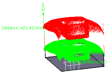
The tool path is displayed on the part.
You can also translate the tool path by selecting it in the viewer,
clicking either on the approach or the retract and dragging.
The contextual menu over the word "distance" lets you choose whether you want to translate the tool path along:- the X axis,
- the Y axis,
- the Z axis,
- or the tool axis.
and then pulling the tool path.
You can also double click Distance and enter a value in the distance dialog box that is displayed.

Double-click anywhere in the viewer to validate and revert to the main dialog box. -
Choose Rotation in the tool path contextual menu.
The tool path is displayed on the part.
You can define the rotation you want with respect to:- a point; this defines the origin for the rotation,
- an edge this defines the rotation axis,
- a plane; the normal to the plane defines the rotation axis,
- or a face; the normal to the face defines the rotation axis.
As you move the mouse over the tool path, the elements that can be used for the rotation are highlighted in red.
By default the rotation is effected around the tool axis.
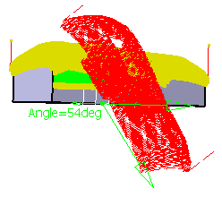
Change the angle by double-clicking on the word Angle in the viewer
(you can also drag the direction arrow in the viewer). A dialog box is displayed.

Enter the number of degrees you want to rotate the tool path by.
For instance, a rotation of 54 will give this result:

Double-click anywhere in the viewer to validate and revert to the main dialog box. -
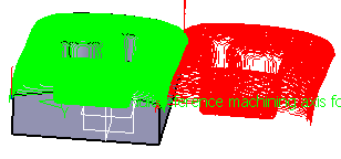
Choose Mirror in the tool path contextual menu.
Choose a plane or a face to be the mirror plane.

Double-click anywhere in the viewer to validate and revert to the main dialog box..
![]()