|
|
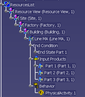
This method describes how to create an end condition for a planned process and how to display it in the context of the process in a 3D view. The definitions of an end condition generally require that the start condition for the process is defined. In order to define a start condition or end condition you have to define the position, the planning status for the start or end condition, and a 3D context for the products or resources linked to the process. Starting with the R17 Release, the Define conditions command can also be used for processes, that have a resource as a parent. See also: Adding an Activity as a Child to a resource. The Define condition command enables you to define the start condition, end condition and 3D context for these processes. In order to define the start condition, end condition or 3D context, you must select a resource with behavior or a process. The following procedure specifies how the defining takes place. According to the specified definition, either the start condition, end condition, or 3D context will be displayed as the child of the resource in the tree (picture below) of the selected resource (Line MA in the example).
|
|
|
|
NotesAn end condition can be created only for planned processes, neither a start condition nor an end condition can be created for simulation processes. |
|
|
|
|
|
|
|
Defining End Conditions |
|
|
With the help of the end condition you can set the
end status for a process as the target of all previously executed
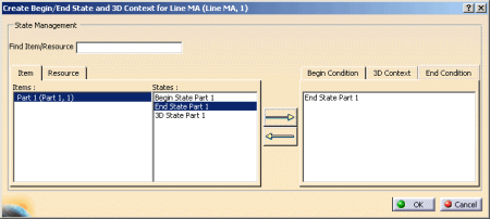
detailed activities for a product or a resource. The end condition is defined for processes in the dialog Create Begin/End State and 3 D Context. |
||
|
1. |
Open the State
Management Tools –
Tools -> State
Management Tools.
|
|
|
2. |
Then click on the icon Define conditions
|
|
|
3. |
Select the process for which the end condition is to be defined. |
|
|
4. |
All linked products are displayed under the tab Item. Select the entry for which you want to define the end condition – in the example it is Part 1. | |
|
5. |
Select the entry under the tab State – in the example it is End State Part 1. Then click on the tab End Condition. | |
|
6. |
Click on the rightward arrow -> in order to define the entry selected under State as the end condition – the defined end condition is displayed under the tab end condition. | |
 |
||
|
7. |
Click OK to confirm the selection. | |
|
The end condition is defined and is displayed in the PPR tree under the node end condition.
|
||
| The defined end conditions are displayed after saving in the Delmia Process Engineer (DPE) under the tab Process has Context 3D state. | ||
|
8. |
Save the project using File->Save in V5. Select the process in the DPE. Then click in the list view on the tab Process has Context 3D state. The defined end conditions are displayed. | |
Displaying Start and End Conditions in the 3D Context |
||
|
|
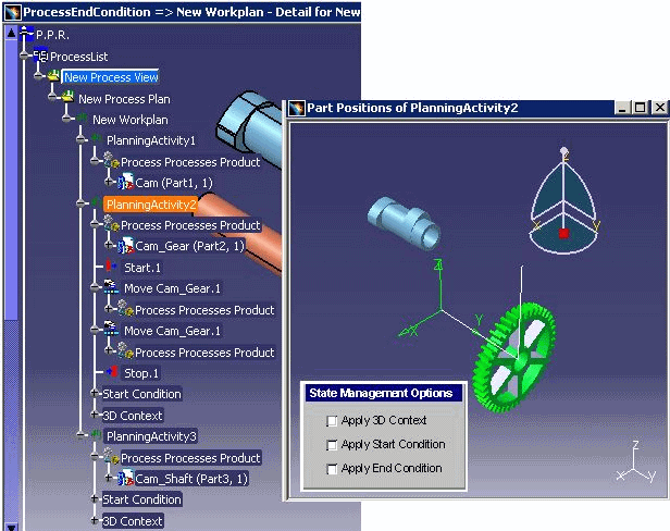
NotesIt is not possible to select start condition and end condition simultaneously but it is possible to select start or end condition together with 3Dcontext. |
|
|
1. |
In order to view the
display in 3D context, click on the icon Show Position of Products
and Resources in Process Context
|
|
|
2. |
Then select the process. The display is shown in a window separate from the 3D view. | |
|
3. |
Select one of the three
options.
|
|
|
4. |
|
|
|
5. |
In order to close the 3D view again, click on the
icon
 |
|
Displaying the End Condition during the Process Verification and Simulation |
||
|
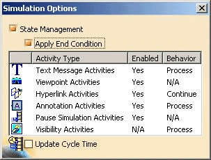
Both fields State Management and Apply End Condition must be active in the dialog Process Verification in order to display the end condition during process verification and simulation.
|
||
|
1. |
Activate State Management and Apply End Condition in order to display the end condition during the process verification and simulation. | |
Settings for the Simulation |
||
|
1. |
In order to display the end condition during the simulation switch to the working area Assembly Process Simulation. | |
|
2. |
See DPM – Assembly Process Simulation -> Simulation Toolbar for information on how to work with the process simulation
The two toolbars Simulation Control Tools and Process Simulation appear in the standard configuration after the simulation is started. |
|
|
3. |
Start the simulation in the toolbar Process Simulation.
|
|
|
4. |
|
|


