 |
This task shows you how to remove and modify cutouts via
the Cutout dialog box. Cutouts are created in parts and are used
for routing objects like pipes through the part.
Cutouts are part features and can also be deleted by
activating the part and selecting Delete from the contextual menu. |
|
1. |
In the
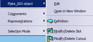
specification tree, right click the plate, select PlateXXX in the drop
down menu that shows, and then Modify/Delete Cutout.

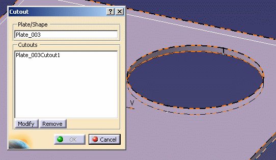
The Cutout dialog box opens. Existing cutouts in your part are
displayed in the box.

|
|
2. |
Select a cutout in
the Cutout dialog box.
The Modify and Remove
buttons become available. |
| |
|
Modifying a Cutout
|
| |
3. |
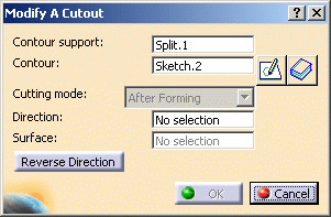
To modify a
cutout, click the Modify button. The Modify A Cutout dialog box displays.

|
| |
4. |
Click in the field
that you want to modify, in this case the Contour field.
The cutting mode cannot be changed but you can modify other attributes
if they were defined when the cutout was created. |
| |
5. |
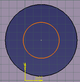
Select the contour
you want to use to replace the existing contour.
You can use an existing contour, or you can use the Sketcher to draw a
new profile. If you are using the Sketcher, you can draw on top of our
existing contour (as shown in the image below) or draw elsewhere in the
part.

|
| |
6. |
Exit the Sketcher,
and click OK in the Modify A Cutout and Cutout dialog boxes.
The cutout is modified. |
| |
|
Removing a Cutout
|
| |
3. |
To remove a
cutout, click the Remove button, then OK to exit. The
selected cutout is deleted. |
 |