|
|
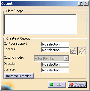
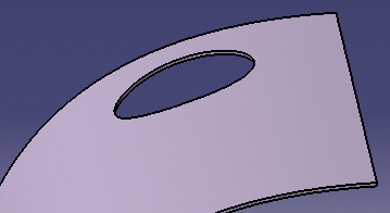
This task shows you how to create cutouts. Cutouts are created in parts and are used for routing objects like pipes through the part. |
||
|
|
1. |
With your document open, click the Cutout button
|
|
| 2. |
Select the part in which you want to make a cutout.
Multi-selection of parts: you can select more than one part (click on the parts in the geometry area or specifications tree) if you want to create cutouts in all selected items at the same time. The Cutting Mode is limited to "After Forming" and the contour must exist in the document. |
||
|
|
3. |
Note: For a multi-selection of parts, the contour must exist in document. Neither sketched nor the catalog contours are available. |
|
| 4. | Define
the contour:
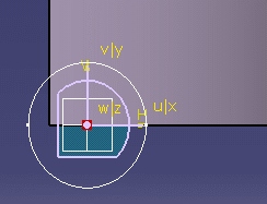
Using the Sketcher
|
||
|
|
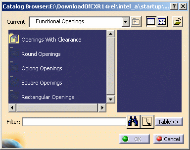
From a CatalogThe Contour field shows the contour you have selected or sketched. |
||
| 4. |
Keep the default cutting mode to create an After Forming cutout. Two cutting modes are available:
|
||
| 5. | Select
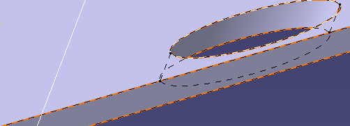
a line that represents the angle you want the cutout to assume.
You can select a line in the part geometry to show this angle. You can also select a line in another object, and the cutout will assume the angle that the other object has to the plate you are working on. |
||
|
|
|||
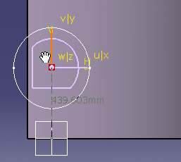
| In the image below the user selected a line to indicate the angle of the cutout. You can see that the cutout angle matches that of the line. | |||
 |
|||
|
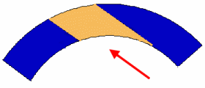
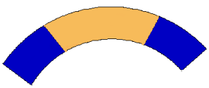
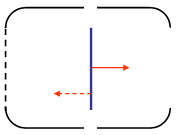
The Reverse
Direction option lets you project the contour used to create
your cutout in the opposite direction.
In our illustration of the passageway in an elevator cage, the contour (in blue) can be projected in one of two directions depending on where you want to locate the doorway. |
 |
||
| 7. |
Click OK to place the cutout. The cutout will be given a name
that will display in the Cutout dialog box. You can add more cutouts or click OK to exit. Each cutout that you create will be given a unique name. |
||
Before Forming Cutting ModeThe cutout you create will be normal to a support surface. To create this type of cutout follow steps 1 thru' 3 above, then: |
|||
| 4. |
Set the cutting mode to Before forming. The Surface field becomes available. |
||
| 5. |
Select the support surface. In the Before forming mode, you must select a support surface. The cutout will be created normal to this surface. |
||
| The Reverse Direction option lets you project the contour used to create your cutout in the opposite direction. | |||
| 6. | Click the OK button to place a cutout . The cutout will be given a name that will display in the Cutout dialog box. | ||
|
|
You cannot copy and paste, or drag and drop cutouts. | ||
|
|
Cutouts are part features and can be deleted by activating the part and selecting Delete from the contextual menu. | ||
|
|
|||
