|
|
An end cut is created on a shape to configure the mating ends for proper connection with another shape or profile and prior to applying a weld connection. A sample feature catalog containing end cuts is provided with the product. An end cut is a parametric object and, when you place one, it will size itself based on the formulas you defined when creating it. | |
|
|
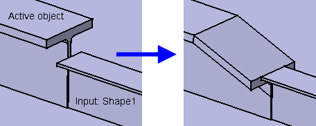
This task shows you how to create a contextual end cut, i.e. a feature with multiple inputs. This feature depends on external objects (other plates, shapes, planes, etc.) to be placed. In our example, you will place an end cut on a large T-beam that must accommodate the smaller T-beam (input - shape1) to make a proper join. The end cut is placed on just one of the objects (called the active object).
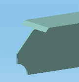
You can also place a standard end cut feature:
|
|
| It is
important to know that this task describes only one behavior, based on
the end cut "gatormouth" that is provided with this application.
Most users will create their own end cuts and the behavior will depend on how they
define those end cuts. For instance, a user could define an end cut such
that it places at both ends of a beam, instead of one end as described
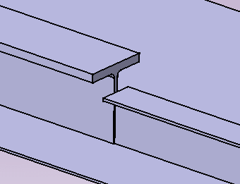
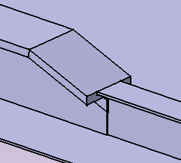
here. The image below shows two beams on which end cuts are to be placed.
|
||
|
|
1. | With your
document open, click the Contextual Endcut
|
| 2. | Double click on
the type of object on which you want to place the end cut, in this case a
tee. You will be asked to select standard or contextual end cuts.
Standard end cut refers to end cuts with one input. Contextual refers to end cuts with more than one input. |
|
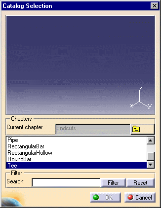
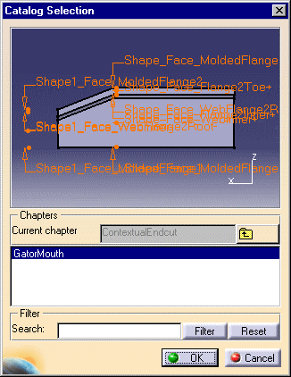
| 3. | Double click on
Contextual Endcut to display the different types of end cuts available to
you in the catalog for this type of object (tee). In this case only a
GatorMouth end cut is in the catalog. If there is only one end cut
available then it will display in the window, as shown here.
|
|
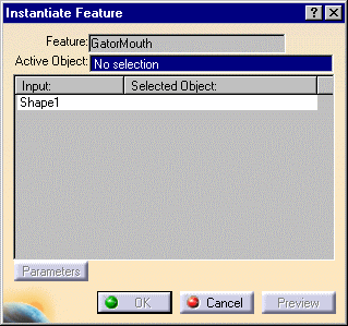
| 4. | Click OK
and the Instantiate Feature dialog box displays.
The Feature field lists the end cut you have selected. |
|
| 5. | Select the active
object on which the end cut will be placed, in our example the large
T-beam. The Active Object field displays displays the part number of the beam selected. |
|
| 6. | Select external
inputs from which information will be obtained before placing the end cut
on the active object, the smaller beam. In our example, there is only one external input: the small T-beam. The part number of the smaller beam displays next to the Shape1 field. |
|
| These are the only inputs required by this end cut. Other end cuts you create may require more inputs, in which case you will be prompted to select them. | ||
| 7. | Click OK
in the Instantiate Feature dialog box to place the end cut.
|
|
|
|
||
