|
|
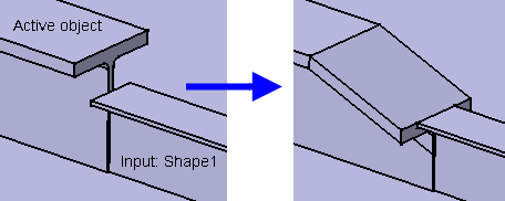
An end cut is created on a shape to configure the mating ends for proper connection with another shape or profile and prior to applying a weld connection. A sample feature catalog containing end cuts is provided with the product. An end cut is a parametric object and, when you place one, it will size itself based on the formulas you defined when creating it. | |
|
|
This task shows you how to create a standard end cut, i.e. a feature with no contextual inputs. This end cut feature does not depend on any external objects (other plates, shapes, planes, etc.) to be placed. You can also modify an existing end cut - see Step 8 to learn how to do it.
You can also place end cuts with contextual inputs:
|
|
|
|
1. | With your product
open, click the Standard Endcut
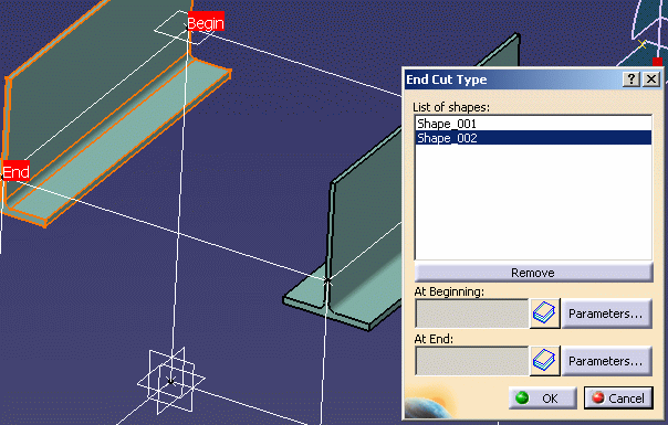
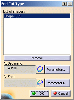
The End Cut Type dialog box opens and the Begin and End points of the shape will be indicated.
You can select more than one shape, with the selected shapes displaying in the List of Shapes window. If you want to remove a shape from the list select it and click Remove. |
|
|
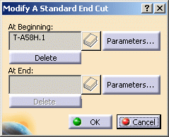
NOTE: You will not be able to select a shape that has end cuts at both ends. If the shape you selected already has end cuts they will display in the At Beginning and At End fields. In that case, you have to use the Modify command to change parameters of an existing end cut. | |
| 2. | Select the Catalog
Browser button to define the Beginning end cut type in the At Beginning
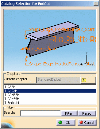
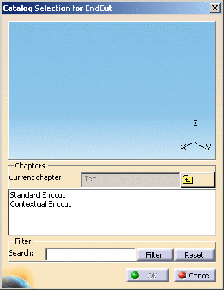
field. The Catalog Selection for Endcut dialog box opens. |
|
 |
||
| 3. | In the Catalog
Selection for Endcut dialog box, double-click Standard Endcut, then
navigate to the chapter and family that contains the appropriate end cut
type for the shape being used.
Standard end cut refers to end cuts with one input. Contextual refers to end cuts with more than one input. Use the Filter button to narrow your search. Use the wild card (*) symbol at the end of the keyword (e.g., ENDCUT*) to include all entries with the keyword "endcut". The selected end cut type will preview in the Catalog Selection for Endcut dialog box. Zoom in to enlarge the image in the preview and to visualize the surface and edge parameters.
|
|
|
|
If the parameters
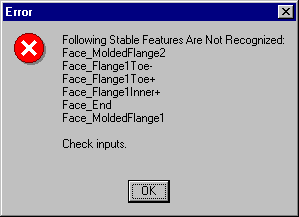
of the end cut do not match those of the shape you will be advised of
mismatched or undefined parameters. An end cut is a feature that resides
in a CATPart; therefore this condition must be corrected using Part
Design.
|
|
| 4. | Click OK in the Catalog Selection dialog box when you have selected the end cut. | |
| 5. | Click
Parameters... in the End Cut Type dialog box.
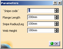
The Parameters dialog box will open. This displays the default parameters for the end cut you selected. The number of parameters will differ depending on the end cut type. Change the parameter values as necessary, then click OK. |
|
 |
||
| This will return
you to the End Cut Type dialog box.
|
||
| 6. | Repeat to define the end cut type at the other end of the shape (at End field). | |
| 7. | Click OK
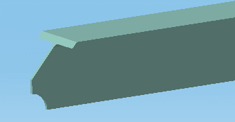
in the End Cut Type dialog box when done. The end cut is created.
|
|
|
|
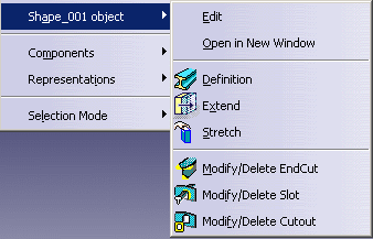
Removing & Modifying EndcutsTo modify endcut parameters or delete an endcut:
|
|
|
|
||
