|
|
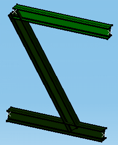
This task shows how to create shapes. The Shape command allows you to create shapes of different sections, including curved or twisted shapes. |
||
|
|
There are two
methods for placing a shape:
|
||
|
|
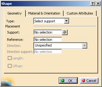
1. | With your product
open, click the Shape
button
The Shape dialog box opens. (If the Type is set to Point to Point then the Point Definition dialog box will also open.) |
|
 |
|||
| 2. | To place a shape on an existing support element, choose Select Support in the Type field. | ||
| 3. | Click the
Material & Orientation tab and select material, grade and section. See
Material Management for more information about selecting
material. Material, grade and section are defined in the specifications catalog. |
||
| 4. | Select the support line on
which you want to create the shape.
The shape is created in preview. |
 |
|
|
|
Note: Multi-selection of
supports is available. To visualize selected supports,
click the List
|
||
Shape OrientationIf the support line is vertical, the web of the shape (local V-axis of section) is oriented toward the Y-axis of the document coordinate system. If the support line is non-vertical, the web is oriented toward the Z-axis of the document coordinate system. In the Shape dialog box, the selected support line will display in the Support field under Placement. |
|||
| In the Material & Orientation tab click the drop-down arrow opposite the Anchor point field to select the desired anchor point for the shape you are creating. | |||
| Use the arrows in the Angle field to rotate the section. The default is in 90 degree increments, but you can change the step. To change it, right click on the Angle field and select Change Step in the drop down menu. | |||
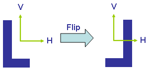
| Use the Flip button to flip the section about its vertical axis.
|
|||
| Click the Custom
Attributes tab to change the values of attributes added by
the user. See Adding/Modifying Custom Attributes. These attributes can also be browsed and edited via the Properties dialog box. |
|||
| 9. | Click OK
when done. The shape is created.
|
||
|
|
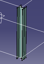
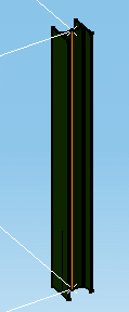
Similarly, you can
create a shape on a curved support line. Using the Select Support method,
simply select a curved line.
|
||
|
|
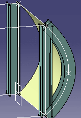
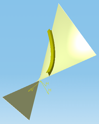
Creating Curved or Twisted ShapesIn the case of a swept or lofted surface in a design where a shape may curve or twist, you can create the shape normal to the surface. This is done using the Reference option in the Shape dialog box. |
||
|
|||
|
|||
 |
|||
|
|
|||
Using Point-to-Point to Create a ShapeThis method requires no support. |
|||
|
|
It lets you place shapes using points, a plane or an axis, and lets you define shape limits in different ways, for example by specifying a length. | ||
|
|
1. | With your product
open, click the Shape icon
The Shape dialog box opens. |
|
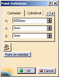
| 2. | To create a shape
using the point-to-point selection method, select Point-to-point in the
Type field.
The Point Definition dialog box will open. |
||
| 3. | Make the necessary changes to the Section, Material, Anchor Point and Orientation settings, and (optional) valuate any attributes. | ||
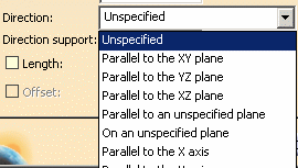
| 4. | In the
Direction list, select how you want to place the shape. You can place shapes using points, a plane or an axis. |
||
 |
|||
Unspecified Planes and Lines
|
|||
Specifying an Offset to the XY, YZ or XZ PlaneSpecifying an offset is particularly useful when creating shapes between existing structures. The offset is computed along the normal to the defined plane.
This option is only available when the selected direction is parallel to the XY, YZ or XZ plane. |
|||
| 5. | Define the
limits of the shape you want to create. You can define the start and end points of a shape in different ways, by:
|
||
Entering Coordinates
|
|||
 |
|||
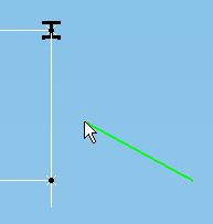
Retrieving Coordinates using 3D CompassYou can use the 3D compass in the Point Definition dialog box to retrieve point coordinates:
|
|||
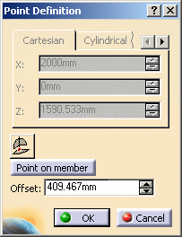
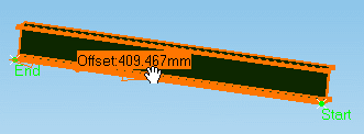
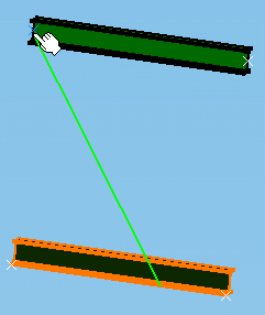
Creating a Point on a Existing ShapeYou can also use the Point on member option in the Point Definition dialog box to define a point on an existing shape: |
|||
|
|||
|
|||
|
|||
Specifying a Length
|
|||
| 6. | Click OK when done. | ||
|
|
|||