|
|
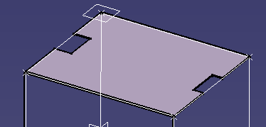
This task shows you how to create plates. Typically plates making up bulkheads, decks and floor plates are planar (flat), while those making up cylindrical or curved walls, sheer and camber decks, and corrugated walls are non-planar (curved) plates. Both planar and non-planar plates can be created using this command. Plates can be created by selecting:
|
||
|
|
1. | With
your product open, click the Plate button
|
|
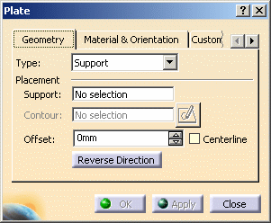 |
|||
| 2. |
Specify how you want to create your plate from the Type drop-down list:
|
||
|
|
Only planar plates can be created using the Support and contour option. | ||
| 3. | Click
the Material & Orientation tab and select material, grade and
thickness. See Material Management for more information. Material, grade and thickness are defined in the specifications catalog. |
||
| 4. | Select
the support plane to which the plate will be applied. The selected plane
appears in the Support field.
|
||
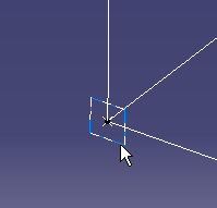
| 5. | Define
the plate contour:
You can define the contour:
|
||
| 6. | Click
Apply when done.
The Plate is created. You can still make changes to the Material and Thickness settings.
|
||
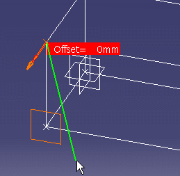
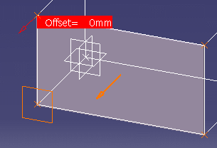
| 7. | In the Offset field, type the distance to offset the plate from the support or use the arrows to set the distance. | ||
|
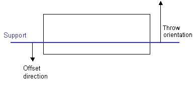
Offset is calculated in the
direction opposite that of the material throw orientation.
In this example we have opted to use the Centerline. This enters a value for the offset corresponding to half the thickness of the material.
|
|||
| 8. | Click the Reverse Direction option in the dialog box or the arrow in the geometry area to extend the plate in the opposite direction from that shown. | ||
|
|
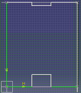
Using the SketcherAlternatively, you can use the Sketcher to sketch the plate contour.
|
||
 |
|||
|
|
A sketch must not contain more than one external plate contour. | ||
|
|||
| 9. |
Click the Custom
Attributes tab to change the values of attributes added by
the user. See Adding/Modifying Custom Attributes. These attributes can also be browsed and edited via the Properties dialog box. |
||
| 10. | Click OK when done. | ||
|
|
|||
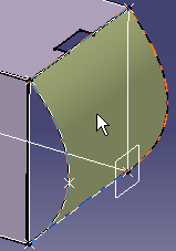
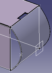
Selecting a Support Surface to Create a PlateYou can create both planar and non-planar plates using this option. The following scenario illustrates a non-planar plate. The support geometry includes a spline and a sweep to create the support surface. |
|||
|
|
1. | With
your product open, click the Plate icon
The Plate dialog box opens. |
|
| 2. | Set the Type to Support. |
|
|
| 3. | Make the necessary changes to the Material, Thickness and Offset settings. | ||
| 4. | Select
the support surface to which the plate will be applied.
The support surface can be planar or non-planar. It cannot be the face of a structural section. The plate is immediately created on the support surface.
|
||
| 5. | Click OK to close the Plate dialog box. | ||
|
|
|||
