 |
-
Select Explode  . .
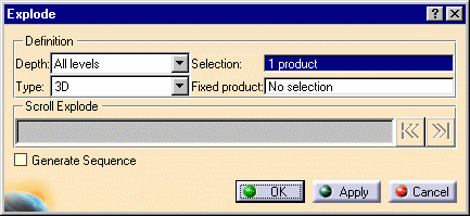
| The Explode dialog box is displayed. |
 |
If you are in a product-view window, you also see the
Manipulation toolbar. |
-
Select the Wheel Assembly (if it is not already selected
by default).
 |
If you are in a product-view window, you can also use the drag
and drop capability (drag the Explode  icon and drop it onto the required product in the specification
tree).
 |
-
Set Depth to All levels (if not
already set).
| The Depth parameter lets you choose between a totally
(All levels) or partially (First level)
exploded view. |
-
Set Type to 3D (if not already
set).
| If you are in a product-view window, you can generate
a sequence from the exploded view, if you select the Generate
Sequence check box before launching the explode operation. |
 |
For more detailed information refer to
Generating a Sequence from an Exploded
View. |
-
Click the Apply button to perform the
operation.
 |
| Note that you can move products within the exploded view using
the 3D compass. |
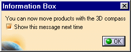 |
| If you are in a product-view window, the manipulation toolbar is
also available once you move an object with the 3D Compass. |
| The Scroll Explode field gradually displays the
progression of the operation. The application assigns directions and
distance. Once complete, the resulting exploded view looks like this: |
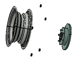 |
| Suppose you are not satisfied with this result because the nuts
are not correctly positioned and the constraints are not respected.
Therefore, you opt to replay the scenario while selecting the
constrained type. |
-
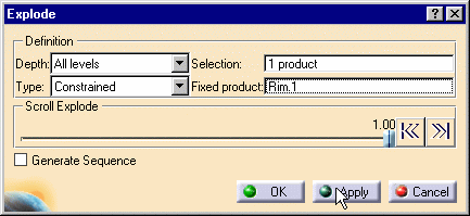
Still in the Explode dialog box, set Type
to Constrained.
-
Select a fixed product: for this task, select Rim1 either
in the specification or PPR tree, or in the geometry area.
-
Click the Apply button to perform the
operation.
 |
| Once complete, the resulting exploded view looks like this: |
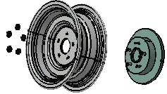 |
| The nuts are correctly positioned, the exploded view corresponds
more to the reality and to a technical documentation. |
-
Select the OK button to confirm the operation
or select the Cancel button to restore the initial view.
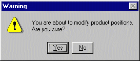
If you select the OK button, the following warning
message is displayed because the exploded view is kept when exiting
the command. In this case, if you need to restore the initial view,
select the Reset  . . |
 |
|
![]()
![]()