and to smooth those scans directly to curves.
- Choose a view parallel to the screen.
- Multi-selection is available.
- Input elements can be:
- clouds of points,
- meshes,
- surfaces,
- volumes (i.e. solids or GSD volumes).
- If input elements are surfaces or volumes, they are
automatically tessellated within the command with a Sag value
which you can edit.
Note that no output mesh is produced. - Cutting planes can be defined by a reference plane, or a guide line, or by independent planes.
- User selection filter can be used to select limiting curves, but not to select the guide curve.
- You can create scans, distinct or grouped, or curves, .
- Grouped output can be grouped in one entity, or by element or by plane.
- With the exception of the input curves and elements, the parameters of the dialog box are modal.
- The action is dynamic on meshes: no need to apply to visualize the
modifications
(position of the reference plane, step, number of planes,...), - In the case of a cloud of points, the intersection may be
interpolated, since the plane does not necessarily
intersect points.
- That problem is reduced with meshes since the plane
intersects facets,
providing a better accuracy.
- If you process an hybrid CloudsUnion element made of a mesh and a
cloud of points,
the planar sections will be created on the mesh only.
-
Click Planar Sections
 .
.
-
Select Polygon.1.
Its name is displayed in the Element field.
A cutting plane is displayed:

-
The cutting planes proposed are parallel to either YZ, XZ or XY depending on which is
perpendicular to the largest edge of the working box of the first element selected. -
Multi-selection is available:
- Click
 to display the list of elements selected.
- Click an element in the graphic area or in the
specification tree to add it to the selection list.
You can also select an element in the list, and click Remove or Replace to modify the selection list.
A contextual menu is also available:
- Click Close to end the selection and revert to the main dialog box.
- Once several elements have been selected, their number is displayed in the Element(s) field.

-
A contextual menu is available on Element:

- Click
-
-
Select Pad.1 as a second element.
Since it is a volume, it will be tessellated. The Sag value becomes editable.
Whenever you modify the Sag value, the tessellation is restarted. -
Define the cutting planes.
You can create parallel sections using either: - parallel planes,
- planes perpendicular to a guide,
- independent planes.
Click the required icon on the left of the dialog box:

Parallel planes:
The cutting planes will be parallel to a Reference plane, that can be:- one of the standard planes
 ,
,
 or
or
 ,
, - a plane defined by the compass
 ,
, - an existing plane

- a plane that you define within the action:
Click .
the Planar Sections dialog box is hidden.
.
the Planar Sections dialog box is hidden.
Pick anywhere in the 3D viewer to define a first point.
A line appears as you move the cursor.
Pick anywhere in the 3D viewer to define a second point.
The Planar Section dialog box is redisplayed and a reference cutting plane is displayed. Its origin is the first point defined, its first direction the vector defined by the two points, the second direction is the vector normal to the screen plane.


Planes perpendicular to a guide:
Select a curve.
Its name is displayed in the dialog box.
The cutting planes will be perpendicular to this curve.
- The degree of the guide must be greater than 2.
- A join (in the Generative Shape Design sense) is not allowed as a guide.
-
You can clear the selection with the contextual menu

Independent planes:
Select a plane. Its name is displayed in the dialog box.
You can select as many independent planes as required using the multi-selection icon.
Their number is displayed in the dialog box.
You can create planes using the contextual menu of the Plane field.

- The parameters Number and Step are not available with this option.
- For a quicker selection, use the Selection Sets capabilities.
-
Except for the independent planes option, a manipulator is displayed on the reference plane.
It can be used to position the reference plane either by dragging the manipulator
or by using the contextual menu Edit.
Keep this point enables you to create the point at the center of the plane.
After setting the orientation of the reference plane, you can move it along its normal or
along the section guide by dragging the center of the green manipulator in the required direction.
-
If the cutting planes are created on the wrong side of the reference plane, click Swap to create them on the right side.
-
Except for the independent planes option, you must decide to freeze either:
Click the parameter you want to freeze.
You can:
-
type the requested values in the Step and Number fields.
-
or use the manipulator available on the last cutting plane proposed.
This manipulator is used to modify either the Step between cutting planes (when Number is selected),
or the Number of planes (when Step is selected)
- A contextual menu is attached to this manipulator.
- Selecting or clearing Fixed number of planes is the same as selecting Number or Step in the dialog box.
-
Keep this point enables you to create the point at the center of the plane.
- Edit enables you to edit the position of the plane.
- An alternative is to select the
Infinite check box.
If the Number of cutting planes is frozen, the step between them will be computed automatically.
If the Step between cutting planes is frozen, the number of cutting planes will be computed automatically.
-
-
The check box Preview is selected by default. It displays the computed planar sections dynamically on the selection. To improve performance, you can clear this check box while you are adjusting the parameters.
Preview is available for meshes, surfaces and volumes, not for clouds of points. -
For clouds of points, the Influence Area parameter defines a computation area around the cutting planes:
-
when the points are not dense, a cutting plane (black line) may be unable to intersect the points.
-
The Influence area is the area shown in yellow that contains the points considered to intersect the cutting plane.
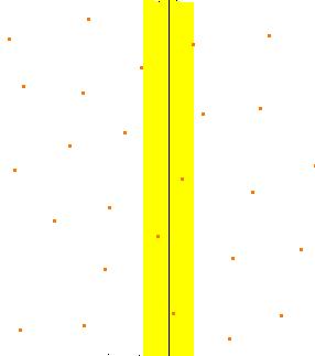
-
You can define its value according to your needs.
-
-
If required, you can select one or two limiting curves for any of the plane option:
-
Place your cursor in the First limiting curve field and select the curve. Its name is displayed in the dialog box.
-
If necessary, repeat this in the Second limiting curve field.
-
You can clear the selection with the contextual menu
- The limiting curves should lay on the element selected.
- The limiting curves must be continuous.
- User selection filter capabilities are available to select a whole entity or one of its component as a limiting curve. See Selecting using a Filter in the CATIA Infrastructure User's Guide for more information.
- When using a limiting curve, the scans may be created on the
"wrong" side of the curve.
In fact, this side is determined by the origin of the reference plane.
So move the reference plane to create the scans on the "right" side, either with the contextual
Edit menu of the plane, or using the compass.
-
-
By default, the planar sections are created as scans (
 is not pressed).
If
is not pressed, you will create scans and only scansHere is a summary of which scans you can create:
You have selected Pad.1 and Polygon.1
You have selected You create 
Scans, as one group of Planar Sections 
Scans, as one group of Planar Sections for each element selected.
The name of the Planar Sections contains the name of the related element.
Scans, as one group of Planar Sections for each plane.
The Planar Sections are created in a different color for each plane. 
Scans, as distinct Planar Sections. 
Click OK to create the scans and exit the dialog box. -
If you want to create curves, click
and click Apply in the Planar Sections dialog box.
A temporary scan is displayed in the specification tree.
The Curve from Scan dialog box is displayed.
The operating mode is the same as for Creating Curve from Scans except that only the curvature comb
(no curvature analysis dialog box) is displayed.
When you are satisfied with the curves, click OK in the Planar Sections dialog box to create the curves and exit the dialog box.-
Curves and only curves will be created.
- If you need a complete curvature analysis of the curves you
create, you have to create the scans first,
and then create the curves with the Curve from Scans action. - When you modify a parameter, click Apply in the corresponding dialog box to take it into account.
-
![]()