- the dialog box of the command,
- how to create split points and internal points,
- how to close the curve,
- how to create a dominant curve section,
- how to edit the curve as you create it,
- how holes in the support mesh are managed.
Dialog Box
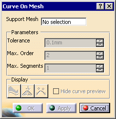
Displays the name of the mesh on which the curve is created.
It can be a multi-cells mesh. Multi-selection is not allowed.
Parameters
The parameters become active once the mesh has been selected.
It is the tolerance used to smoothed the scan formed by the points picked and the intermediate points, i.e. the maximum allowed distance between the resulting curve and the points of the scan.
Maximum order of the curves created, i.e. the number of control points of those curves.
Maximum number of spans between two cutting points.
with the least possible number of segments of the least possible order. I.e.:
- the command tries to create a curve with one segment of order 2.
- If the tolerance is not reached, the order of the segment is increased up the the Max. Order value.
- If the tolerance is not yet reached, the number of segments is
increased, the segments having the least possible order.
This order is increased to meet the tolerance, then the number of segments,
and so on until both the maximum order and the maximum number of segments are reached.
You can check the segmentation and the order of the curves with the
![]() icon.
icon.
Display
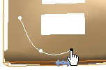
By default, you are in running point mode,
i.e. the curve is updated in real time and the projection of the cursor on
the mesh indicates the next pick.
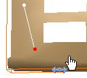
Select the Hide curve preview check box to exit the running
point mode. The last picked end point is colored in red, and there is no
indication of the next pick.
![]() analyzes the curvature
of the resulting curves.
analyzes the curvature
of the resulting curves.
![]() displays the maximum
deviation.
displays the maximum
deviation.
![]() displays the order and the
number of segments.
displays the order and the
number of segments.
Creating Split Points and Internal Points
Types of Points
Split points are the points
you pick to create the curve.
The two curve sections connected at a split point are constrained.
They are displayed in white.
Intermediate points are construction points, computed automatically between two split points. They lie on the mesh. They form a scan with the split points. This scan is smoothed to create the curve. They are not visible.
Internal points are not
split points and have the same behavior as intermediate points, i.e. they
are intermediate points that are not computed by the command but picked by
you.
They are displayed in dark grey.
Types of Constraints
The symbol under the cursor indicates the current type of constraint.
Picking a point on the mesh will create a new point with that constraint.
![]() indicates a
point continuity (G0 continuity),
indicates a
point continuity (G0 continuity),
![]() indicates a
tangent continuity (G1 continuity),
indicates a
tangent continuity (G1 continuity),
![]() indicates an internal point.
indicates an internal point.
Use the contextual menu to select a type of constraint

or press Shift to go from one symbol to another.
Press Ctrl+Shift to visualize all the constraints
of the current curve.
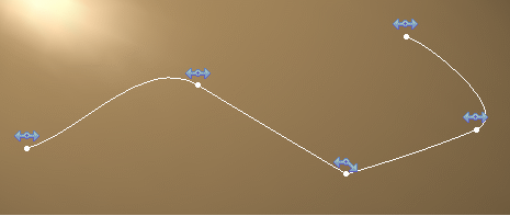
Closing the Curve
Move the cursor close to the start point.
The symbol under the cursor turns to
![]() .
.
Pick to close the curve.
Creating a Dominant Curve Section
A dominant curve section is a section of the curve between two split points which enforces a tangent continuity at those points.
Pick a point and drag the cursor. The symbol turns to
![]() ,
that indicates you are in dominant creation mode.
,
that indicates you are in dominant creation mode.
Release the cursor and pick the next split point to create a dominant curve
section (You exit the dominant creation mode automatically as you pick the
split point).
Online Edition
Online edition lets you edit the curve while you are creating it (move a point, remove a point, modify continuity constraints...). Hold down Ctrl to work in online edition mode:
- the scan formed by the split points and the intermediate points is
displayed in cyan,
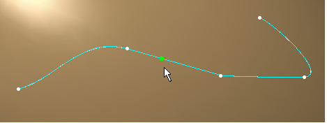
- when you pass the cursor close to a split point, it turns red, the
constraint symbol is displayed and you can drag the point to another
location.
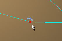
You can also pick the constraint symbol to go from one type to another. - when you move the cursor along the scan, a green dot is displayed
corresponding to intermediate points.
Pick an intermediate point to insert a split point or an internal point, depending of the current type of constraint.

- use the contextual menu to change the type of constraint or remove a
point

- when you move the cursor over a section of the curve, you can see if
it is a dominant curve section
 or not
 .
.
Pick the symbol to go from one status to the other.
Management of Holes
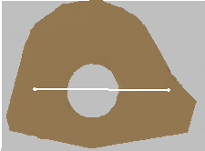
When there are holes in the support mesh, the curve is interpolated on
the hole area as shown below:
