Creation mode
Two creation modes are proposed:
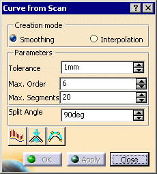
Smoothing
In the Smoothing
creation mode, the curve is created by smoothing all the points between two
split points.
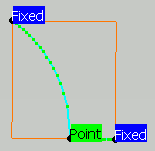
Three parameters are available in this mode:
Tolerance is the maximum distance between the curve and the points.
- Decrease the value of Tolerance to reduce that distance.
-
You can check the distance between the curve and the
points with the
 icon.
icon. -
If the tolerance is met, the computed curve is displayed
in white.
If the maximum deviation display is activated, the maximum error is displayed in green.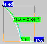
-
Otherwise, the computed curve is displayed in red.
If the maximum deviation display is activated, the maximum error is displayed in red.
Max. Order is the maximum order of the curves created, i.e. the number of control points of those curves.
Max. Segments which is the maximum number of spans between two cutting points.
with the least possible number of segments of the least possible order. I.e.:
- the command tries to create a curve with one segment of order 2.
- If the tolerance is not reached, the order of the segment is increased up the the Max. Order value.
- If the tolerance is not yet reached, the number of segments is
increased, the segments having the least possible order.
This order is increased to meet the tolerance, then the number of segments,
and so on until both the maximum order and the maximum number of segments are reached.
You can check the segmentation and the order of the curves with the
![]() icon.
icon.
Interpolation
In the Interpolation
mode, the curve is created by interpolating the points of its support scan.
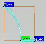
No parameters are proposed for this mode
Visualization and Analysis icons
Three visualization buttons are available:
![]()
![]()
![]()
Push the buttons to activate the display, release the icon to erase the
display.
Those three displays can be combined together.
![]() analyzes the curvature
of the resulting curves:
analyzes the curvature
of the resulting curves:
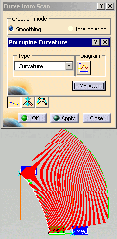
- This is a temporary analysis, no analysis element is created in the specification tree.
- Click More... to display more analysis options.
- Click Less to display the quick analysis options
- More information is available in the Curvature Analysis section.
![]() displays the maximum
deviation (not available for the Interpolation mode):
displays the maximum
deviation (not available for the Interpolation mode):

The label is green if the tolerance is met, otherwise it is red.
![]() displays the order and the
number of segments (not available for the Interpolation mode):
displays the order and the
number of segments (not available for the Interpolation mode):
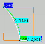
When the curve computed is segmented, the segmentation is displayed
with blue x symbols.
This color and symbol are not editable.
Split angle
A split angle
is proposed by default at 90 degrees. This value is editable.
Whenever the computed curve forms an angle greater than this value, it is
split automatically into two curves.
The split point is displayed and two curves are created.
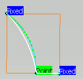
the display of the split points is updated. Click Apply to update the display of the computed curves.
Split points and End points
-
add split points by picking points of the scan.
-
or move a split point to another point of the scan:
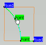
-
pick the split point you want to move: press the control key and the left-click on the label of the split point,
-
with the control key and the left button of the mouse still pressed, drag the split point
to the required scan point and drop it there.
-
-
set a constraint on a split point:
- The default constraint on a split point is Point, i.e. passage.
- Click the green label to change it to Tangent. A second click will return it to Point.
-
right-click a split point to access its contextual menu:

End points
End points propose more items in their contextual menu.
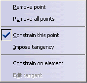
- You can remove the extremity point of a computed curve, and
replace it with a new or existing split point.
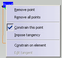
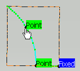
The end point is removed:
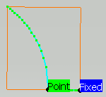
Pick a point on the scan:
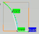
Click Apply to visualize the new curve:
-
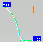
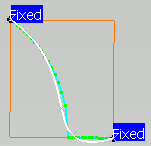
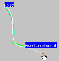
You can free or constrain the end points by checking the appropriate option in the contextual menu.
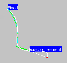
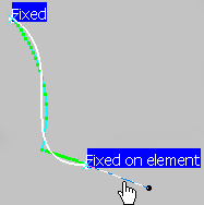
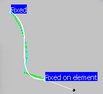
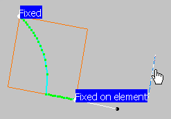
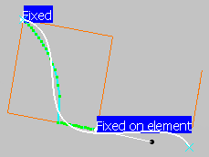
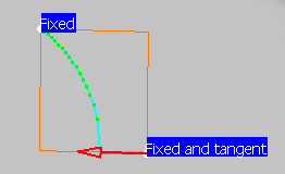
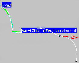
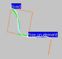
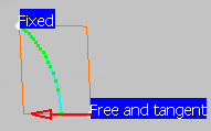
Label Meaning O O O Not available Free The extremity is free X O O Not available Fixed The extremity is fixed, it is the scan extremity (this is the option by default) X O X Not available Fixed on element If the element is a point, the extremity of the curve is this point, not the scan extremity
If the element is a curve, the curve extremity is the nearest extremity of the constraining curve
If the element is a plane, the curve extremity is the point of the plane nearest to the scan extremity
X X O Available Fixed and tangent The tangency direction is given by a vector going through the first (or the last) two points of the scan.
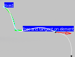
X X X Available Fixed and tangent on element The extremity is fixed and tangent to the constraining element.
O O X Not available Free on element The extremity is free and depends on the element.
O X O Available Free and tangent The extremity is free. The tangency direction is given by a vector going through the first (or the last) two points of the scan.
O X X Available Free and tangent on element The extremity is free and depends on the element. The tangency direction is given by the element (plane or curve).
- The extremity of the curve computed is the scan extremity, unless the
Constrain on element
option is
selected.
- If the constraining element is a point, the curve extremity is that point,
- if the constraining element is a curve,
the computed curve extremity is the nearest extremity of the constraining curve, - if the constraining element is a plane,
the curve extremity is the orthogonal projection of the scan extremity on to the plane.
- If an extremity is constrained on an element, and if a tangency is
imposed, the tangency direction is given by:
- the tangent vector of the curve on the constraining curve extremity,
- or the normal to the constraining plane.
- Whenever the Impose tangency is checked, you can modify the
tangent vector with the following box
(Edit tangent in the contextual menu):
- It is useful to impose a tangency constraint at the extremities
if you intend to reconstruct a part in two steps:
- reconstruction of the first half of the part,
- recovery of the whole part by performing a symmetry.
The tangency constraint will ensure that the two halves fit perfectly.
- Only the tangency direction is taken into account, the norm is not.
