 |
This task will show you how to create a curve totally lying
on a mesh:
- you will pick points on the mesh
(picking non-existing points or features other than the support mesh is not
allowed),
- you can change the view orientation while creating the curve,
- the mesh can be a multi-cells mesh,
- you can control the continuity of the Curve on Mesh,
- you can create a multi-cells Curve on Mesh,
- you can create a closed Curve on Mesh,
- some graphical and statistical information are available during
creation,
- the output 3D curves on mesh are features, hence they are associative
and editable.
|
 |
- Split points are the points picked to create the Curve on Mesh.
Intermediate points are
automatic construction points between the split points.
They lie on the mesh and form a scan that is then smoothed to create the
curve.
Click
here for more information on the type of points.
- Please read the
Parameters for Curve on Mesh chapter for an optimal use of the
command. This chapter describes:
|
 |
Open the
FreeEdges1.CATPart model the from the samples directory. |

|
-
Click Curve on Mesh
 . .
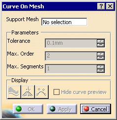
The Curve on Mesh dialog box is displayed.

-
Select the mesh that will support the curve.
Multi-selection is not allowed but the mesh can be a multi-cells mesh.
Its name is displayed in the dialog box and the rest of the dialog box
becomes active.
-
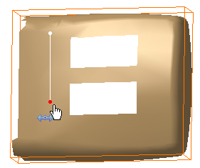
Pick points on the mesh to create the
curve:

-
The points you pick are the split points of the curve.
They are projected on the mesh, along the view direction. Intermediate points are automatically computed between each couple of
split points, and the resulting scan is smoothed to create the curve.
You can adjust the Tolerance of smoothing, as well as the
maximum order (Max. Order) and maximum number of segments (Max.
Segments) of the curve.
-
Click OK to create the curve and exit the
dialog box.
|
|

|