It also shows links to external references and explicitly provides the name of the documents containing these references.
If the specification tree already lets you see the operations you performed and re-specify your design, the graph displayed by the Parent and Children capability proves to be a more accurate analysis tool. We recommend the use of this command before deleting any feature.
-
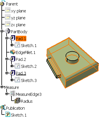
Right-click Pad 1 and select Show All Children .
You can now see that Sketch 2 and Sketch 3 have been used to create two additional pads.
Here is the exhaustive list of the diverse contextual commands allowing you to hide parents and children. These commands may prove quite useful whenever the view is overcrowded.
- Show Parents and Children
- Show Children
- Show All Children
- Hide Children
- Show Parents
- Show All Parents
- Hide Parents
-
Right-click Sketch.1 and select Show Parents and Children.
We can see that Sketch.1 has been created on xy plane. Moreover, you can see that it is a published element.
-
Now, select EdgeFillet1 in the graph.
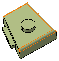
The application highlights the fillet in the specification tree, in the graph and in the geometry area.
-
Position the cursor on EdgeFillet1 and select the Show Parents and Children contextual command.
The parent Pad.1 is displayed.
- Double-clicking on the components alternately shows or hides parents and children.
- The Edit contextual command can be accessed from any element. For example, right-click EdgeFillet.1 and select Edit. The Edge Fillet dialog box appears. You can then modify the fillet. When done, the Edge Fillet dialog box closes as well as the Parents and Children window close and the fillet is updated.
-
Close the window and select MeasureEdge3 from the specification tree.
-
Select Tools > Parent/Children...
The graph that displays shows Pad.2 as MeasureEdge3's parent.
-
Right-click and select Show All Parents.
Sketch.2 as Pad.2's parent is now displayed. In turn, Sketch.2's own parent Pad.1 is displayed and so on.
Parent/Children Applied to Dress-Up Features
previously created. The geometry of this feature is then considered as parent to the dress-up feature.
As design goes on, the application computes specifications from the geometry preceding dress-up features. This geometry can then be different from the initial geometry used to build dress-up
features if you have inserted intermediate features.
Applying Parent/Children to a dress-up feature does not display the most recent geometry preceding the feature in the specification tree. The capability always displays the geometry initially used as the parent of the dress-up feature. Conversely, when editing a dress-up feature, the application always shows the geometry used to compute the feature. These different behaviors explain why for a given dress-up feature, the geometry displayed by the application depends on whether using Parent/Children or Edit. The parents displayed for a dress-up feature are not necessarily the features preceding it in the specification tree.

