![]()
The instantiation of a User Feature can provide an inconsistent result according to the orientation of the geometry of its inputs. This topic is designed to help those of you who want to manage the orientation of their User Feature inputs.
|
|
When instantiating a User Feature manually, you can toggle the green direction arrow in the geometry to get the correct orientation. See example below. |
Open the PktManagingPlanes.CATPart file.
From the Standard menu, select Insert > Instantiate from Document....
In the File Selection window, select the PktPlaneUDF.CATPart file and click Open.
The Insert Object dialog box is displayed. Select:
|
|
|
Reverse the direction of the zx plane and xy plane and click OK when done. The User Feature is instantiated.
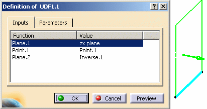
Double-click UDF.1 in the specification tree. The Definition box of the User Feature is displayed. Note that even if the selected inputs are both planes, in the first case (Plane.1), the display shows the zx plane as selected, and in the second case (Plane.2), the display shows a new element (Inverse.1) which was created and inserted at instantiation. Click Cancel to exit the dialog box.
Open the PktPlaneUDF.CATPart file and double-click the User Feature:
|
|
Go back to the PktManagingPlanes.CATPart file and double-click the UDF1.1.
|
 |
|
|
 |
![]()
|
|
To avoid bad orientations when automating the instantiation of a User Feature (UDF) from Visual Basic or Business Process Knowledge Template, integrate control User Features that change the orientation of the geometry in the design of your User Features depending on your needs and on the rules you set. |
|
|
In the example below, you want to create a multisection based on a UDF taking 2 lines in input. This UDF would be corrected whatever the orientation of the lines. |
In the test case described below, you want to instantiate 2 multisections planes into a CATPart. This part contains 3 lines: 2 of them have the same orientation, the other one does not.
 |
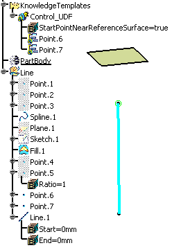
PktCurveOrientation.CATPart. In this model, you have created a spline
built on Point.1, Point.2, and Point.3. Point.4 and Point.5 are the
spline ends (ratio 0 and 1). You can select the orientation of the line
by valuating the StartPointNearReferenceSurface parameter. This parameter
is driven by a rule (Rule.1). Point.6 is valuated by Point.4 and Point.5
through the parameter, the rule and the positioning of the points to the
plane. Point.6 is the result of the UDF. The rule enables you to valuate
Point.6 using the point that is the closest to the plane. The formula
enables you to deduce Point.7 from Point.6.
You create the control UDF (Line) that will be instantiated. The following items are inserted into this UDF:
The inputs of the UDF will be a fill and a spline. |
![]()

 |
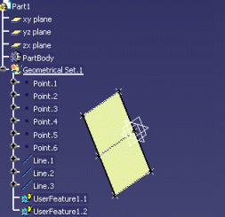
PktRobustMultiSection.CATPart The control User Feature created in the PktCurveOrientation.CATPart file is going to be instantiated into this Part. In this file, both lines have an opposite direction. This Part is made up of the following items:
When instantiating the User Feature, the inputs selected in the geometry are Line.1 and Plane.2. |

After instantiating the User Feature, you want to create a multisections surface. For this surface to be correctly created, both lines must have the same orientation.
 |
 |
| In the graphic above, both lines have the same direction because one of them is constrained by the robust line. The surface can be created. | The graphic above shows what would happen without robust UDF: The robust line is not instantiated and both lines have an opposite direction. The surface cannot therefore be created. |

STEP 3: Creating a UDF based on the multisections surface |
|
 |
After creating the multisections surface, you create a
User Feature that will embed the following items:
|

PktMultiSectionTarget.CATPart: You instantiate the User Feature that you created. The control UDF controls the orientation of the line thanks to the embedded rule that drives the StartPointNearReferenceSurface parameter.
 |
 |
| In the graphic above, both lines have the same direction because one of them is constrained by the User Feature. The surface can be instantiated twice. | The graphic above shows what would happen without robust
User Feature: the User Feature is not instantiated and both lines have an opposite direction. The surface can be instantiated once because Line.2 and Line.1 have the same direction. But it cannot be instantiated another time because Line.1 and Line.3 don't have the same direction. |