![]()
Definition:A GSMLine is a line :
For more information about lines, see Generative Shape Design User's Guide. |
 |
Attributes: |
|
LineType |
|
| A line is defined by its type. The attribute to be used is LineType. The syntax to be used is: LineType = i, i corresponding to the type of line that you want to create. | |
| Please find below an equivalence table listing the existing types of lines that you can create and the digit to indicate. | |
| Line Type in GSD | Line Type in the Package | Corresponding digit | |
| Point to Point | GSMLinePtPt | 0 | |
| Point-Direction | GSMLinePtDir | 1 | |
| Angle to Curve | GSMLineAngle | 2 | |
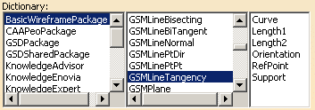
| Tangent to Curve | GSMLineTangency | 3 | |
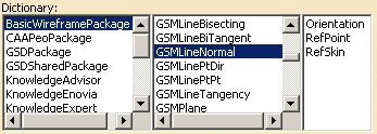
| Normal to surface | GSMLineNormal | 4 | |
| Intersection betw. 2 planes | GSMLineBiTangent | 5 |
| As mentioned above, you may create 7 different line sub-types. Please find below a description of each sub-type, as well as its attributes and the syntax to use. | |||
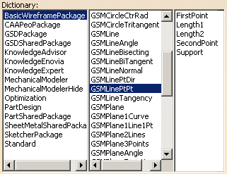
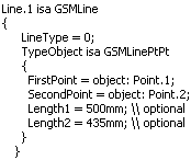
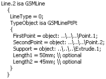
Point to Point Line (GSMLinePtpt)The sub-type to be used in this case is GSMLinePtpt which defines the line extremities. The following attributes are available for this sub-type:
These attributes can be combined as follows: |
|||
| 1st combination | 2nd combination | ||
|
|
||
|
|
|
||
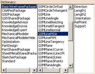
Point-Direction (GSMLinePtDir)The sub-type to be used in this case is GSMLinePtDir which defines the line direction. The following attributes are available for this sub-type:
|
|||
|
These attributes can be combined as follows: |
|||
| Combination | |||
|
|||
Tangent to Curve (GSMLineTangency)The sub-type to be used in this case is GSMLineTangency. The following attributes are available for this sub-type:
These attributes can be combined as follows: |
|||
| Combination | |||
|
|||
Normal to surface (GSMLineNormal)The sub-type to be used in this case is GSMLineNormal. The following attributes are available for this sub-type:
These attributes can be combined as follows: |
|||
| Combination | |||
|
|||