Part Design Package

Please find below a table listing the types available in the Part Design package.

Box Chamfer Cone
Counterbored Hole Counterdrilled Hole Countersunk Hole
Cylinder Hole Pad
Pocket RemoveFace ReplaceFace
Shaft Shell SimpleHole
SoldCombine Split TaperedHole
Thickness ThickSurface Torus
 

Box

Definition:

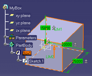
A box is a pad extruded from a rectangular sketch.

Attributes:
  A box is defined by the following attributes:
  • Length which is the pad first limit. The syntax to be used is Length = 10mm.
  • Width which is the pad width. The syntax to be used is Width = 20mm.
  • Height which is the pad height. The syntax to be used is Height = 12mm.
MyBox isa CATPart
 {
 BoxPart isa Part 
  {
   PartBody isa BodyFeature
    {
     // Create a box
     Box1 isa Box
       {
        // Specify the box properties
        Width = 20.0 mm ;
        Height = 25.0 mm ;
        Length = 15.0 mm ;
       }
     }
   }
 }   
   

Chamfer

Definition:

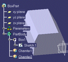
A cut through the thickness of the feature at an angle, giving a sloping edge.

Attributes:
  A chamfer is defined by the following attributes:
  • Angle. The syntax to be used is Angle = 20 deg;
  • Length1. The syntax to be used is Length1 = 5 mm;
  • Length2. The syntax to be used is Length2 = 5 mm;
Important Notes:
  • A chamfer has a Length2 attribute which is the default chamfer length. You don't have to manipulate this attribute in a script.

To specify a chamfer within your script, you must have a part open, then:

  1. Create a Chamfer by using the isa function
    Chamfer1 isa Chamfer ( ) { }

  2. Right-click anywhere inside the parentheses and select Get Edge or Get Surface. Then, in the geometry area, select the edge or surface to be chamfered.

MyBox isa CATPart
  {
    BoxPart isa Part
      {
        PartBody isa BodyFeature
          {
            // Create a box  
            Box1 isa Box
              {
                Width = 20.0 mm ;
                Height = 25.0 mm ;
                Length = 15.0 mm ;
              }
            // Create a chamfer
            // The edge definition must be captured
            // from the geometry area
            // Use Get Edge from the contextual menu
            Chamfer1 isa Chamfer (Edge Definition)
              {
                Angle = 20 deg;
                Length1 = 5 mm ;
              }
            Chamfer2 isa Chamfer (Edge Definition)
              {
                Angle = 30 deg;
                Length1 = 10 mm ;
              }
          }
       }
   }   
 

Cone  

Definition:

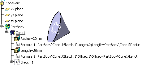
A cone is a shaft created by rotating a triangular sketch.

Attributes:
 
A cone is defined by the following attributes:
  • Length. The syntax to be used is Length = 15.0 mm ;.
  • Radius. The syntax to be used is Radius = 20.0 mm ;.
MyCone isa CATPart
   {
     ConePart isa Part
       {
         PartBody isa BodyFeature
           {
             // Create a cone
             Cone1 isa Cone
                {
                  Radius = 20.0 mm ;
                  Length = 15.0 mm ;
                }
            }
        }
  }
   

Counterbored Hole

Definition:

A mechanical feature of Hole type you create when you click the icon in the Part Design workbench. For more information, see the Part Design User's Guide.

Attributes:
 
A counterbored hole is defined by the following attributes:
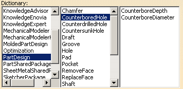
  • CounterboreDepth. The syntax to be used is CounterboreDepth =12mm.
  • CounterboreDiameter: The syntax to be used is CounterboreDiameter =15mm.


Counterdrilled Hole

Definition:

A mechanical feature of Hole type you create when you click the icon in the Part Design workbench. For more information, see the Part Design User's Guide.

Attributes:
 
A counterdrilled hole is defined by the following attributes:
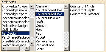
  • CounterdrillAngle. The syntax to be used is CounterdrillAngle = 22deg.
  • CounterdrillDiameter. The syntax to be used is CounterdrillDiameter =12mm.
  • CounterdrillDepth. The syntax to be used is CounterdrillDepth =12mm.


Countersunk Hole

Definition:

A mechanical feature of Hole type you create when you click the icon in the Part Design workbench. For more information, see the Part Design User's Guide.

Attributes:
 
A countersunk hole is defined by the following attributes:
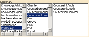
  • CountersinkAngle. The syntax to be used is CountersinkAngle = 12deg.
  • CountersinkDepth. The syntax to be used is CountersinkDepth =15mm.
  • CountersinkDiameter. The syntax to be used is CountersinkDiameter =15mm.


Cylinder   

Definition:

A cylinder is a pad created by extruding a circular sketch.

Attributes:
 
A cynlinder is defined by the following attributes:
  • EndLimit\Length. The syntax to be used is Length =12mm.
  • Radius: The syntax to be used is Radius =5mm.
Cylinder1 isa CATPart
  {
    Part isa Part
     {
       PartBody isa BodyFeature
         {
           // Create a cylinder
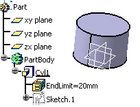
           Cyl1 isa Cylinder
              {
                Radius=15.0 mm;
                EndLimit=20.0 mm;
              }
         }
     }
  }
   

Hole  

Definition:

A  is an opening through a feature.

Attributes:
 
A hole is defined by the following attributes:
  • BottomAngle
  • BottomType
  • Depth
  • Diameter
  • DiameterThread
  • HoleType
  • LimitType
  • Pitch
  • TapSide
  • Threaded
  • ThreadingDepth
  • Radius
To specify a hole within your script, you have to use one of the holes listed below. Hole is the father type and cannot be used.
   

Pad  

Definition:

A pad is a feature created by extruding a sketch.

Attributes:
  A pad is defined by the following attributes:
  • the sketch the pad is extruded from.
  • the FirstLimit\Length (or StartLimit\Length)
  • the SecondLimit\Length ( or EndLimit\Length).
A limit which is not specified is set by default to zero.
// Use Insert File Path from the
// contextual menu to specify the path of the file
// to be imported

import
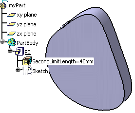
PktSketchToImport.CATPart;/*In the script above, the P0 pad is created from the Sketch.1 sketch which is imported from the  document.*/


myDocument isa CATPart
  {
    myPart isa Part
      {
        PartBody isa BodyFeature
          {
            Sketch isa Sketch.1
            {}
            P0 isa Pad("Sketch")
            {
             SecondLimit\Length=40.0mm;
            }
          }
      }
  }


Shaft  

A shaft is a feature created by rotating a sketch around and axis.
Attributes:
 
A shaft has two attributes:
  • The StartAngle. The syntax to be used is StartAngle=12deg.
  • The EndAngle. The syntax to be used is EndAngle=23deg.
  • The MergeEnd
  • The NeutralFiber
  • The Thickness1
  • The Thickness2
  • The Thinmode
The sketch to be rotated must be imported from an external CATPart document. This external document must also include a rotation axis.
/* Use Insert File Path from the contextual menu to select the  the sketch to be imported */

import //Use the Insert File Path command to insert the Pktsketch_shaft.CATPart file.
MyShaft isa CATPart
  {
    myPart isa Part
      {
        PartBody isa BodyFeature
          {
            Sketch isa Sketch.1 {}
            S0 isa Shaft("Sketch")
               {
                 StartAngle = 20 deg ;
                 EndAngle = 300 deg ;
               }
          }
      }
  }


Shell  

Definition:

A shell is a hollowed out feature.

Attributes:
 
A shell is defined by the following attributes:
  • DefaultInsideThickness. The syntax to be used is DefaultInsideThickness = 2mm.
  • DefaultOutsideThickness: The syntax to be used is DefaultOutsideThickness = 1mm.
To specify a shell within your script, you must have a part open, then:
  1. create a Shell by using the isa function
    Shell1 isa Shell ( ) { }

  2. right-click anywhere inside the parentheses and select Get Surface. Then, in the geometry area, select the face to be hollowed out.

 A 1mm thick shell is created by default. 

MyBox isa CATPart
  {
    BoxPart isa Part
     {
       PartBody isa BodyFeature
        {
         Box1 isa Box
          {
           Width = 20.0 mm;
           Height = 25.0 mm;
           Length = 15.0 mm;
          }
       Shell1 isa Shell (face definition)
          {
           DefaultInsideThickness = 2mm;
           DefaultOutsideThickness = 1mm;
          }
       }
    }
}                        
 

SimpleHole    

Definition:

A mechanical feature of Hole type you create when you click the icon in the Part Design workbench. For more information, see the Part Design User's Guide..

Attributes:
 
 
Hole1 isa CATPart
{
   Part isa Part
     {
         PartBody isa BodyFeature
         {
             P isa Pad
               {
               }
F isa SimpleHole("Use the Get Edge command to select the edge")
              {
              }
         }
     }
}

Sphere  

Definition:

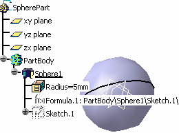
A sphere is a shaft created by rotating half a circle around an axis passing through the arc extremities. The only property is the Radius.

Attributes:
 
A sphere is defined by the following attribute:
  • Radius. The syntax to be used is: Radius = 20.0 mm.
MySphere  isa CATPart
 {  
   SpherePart isa Part
    {
      PartBody isa BodyFeature 
       {
         Sphere1 isa Sphere
           {
            Radius = 20.0 mm ;
           }
       }
    }
}   
   

Tapered Hole

Definition:

A mechanical feature of Hole type you create when you click the icon in the Part Design workbench. For more information, see the Part Design User's Guide.


Attributes
  A tapered hole is defined by the following attribute:
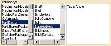
  • TaperAngle:


Thickness

Definition:

A thick

Attributes
  A thickness is defined by the following attribute:
  • DefaultThickness:
   

ThickSurface  

Definition:

A thicksurface is a surface to which material was added in two opposite directions.

Attributes:
 
A thicksurface is defined by the following attributes:
  • TopOffset, the thickness in one direction. The syntax to be used is TopOffset = 0.5mm.
  • the BotOffset,  the thickness in the one direction. The syntax to be used is BotOffset = 10 mm.
myThickSurface isa CATPart
  {
    myPart isa Part
       {
 OpenBody1 isa OpenBodyFeature
   {
             P1 isa GSMPoint
               {
                 PointType = 0;
                 TypeObject isa GSMPointCoord
                    {
                      X = 0mm;
                      Y = 0mm;
                      Z = 0mm;
                    }
                }
             C isa GSMCircle
                {
                  CircleType = 0;
                  TypeObject isa GSMCircleCtrRad
                    {
                       Center = object : ..\..\P1;
                       Support = object : ..\..\..\`xy-plane`;
                       Radius = 150mm;
                    }
                   StartAngle = 0deg;
                   EndAngle = 360deg;
                 }
             Fi isa GSMFill
                 {
                   Boundary = object : ..\C;
                 }
     }

           PartBody isa BodyFeature
       {
              Thick1 isa ThickSurface
    {
    TopOffset = 0.5mm;
    BotOffset = 10 mm;
    Surface = object : ..\..\OpenBody1\Fi;
          }
}
    }
}
 

Torus    

Definition:

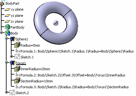
A torus is a shaft created by rotating a circular sketch around an axis.

Attributes:
 
A torus is defined by the following attributes:
  • InnerRadius
  • SectionRadius
BodyDoc isa CATPart
   {
   BodyPart isa Part
     {
      Body isa BodyFeature
        {
        // Create a sphere
        Sphere1 isa Sphere
            {
            Radius = 15.0 mm;
            }
         // Create a torus
        Torus1 isa Torus
         {
         InnerRadius = 20.0 mm ;
         SectionRadius = 10.0 mm ;
         }
      }
     }
}