|
 |
|
Note that:
|
||
CATIA Knowledgeware Infrastructure |
|
| Relations Parameters Formulas Design Tables |
Tips and Techniques - SummaryThis part is intended for those of you who need a quick answer to their questions about the Knowledgeware capabilities. However, using this part requires a prerequisite knowledge of the CATIA basic concepts. |
Reordering Relations Sets and Parameters Sets
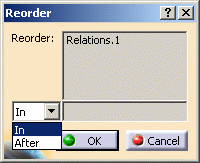
You can now reorder parameters sets and relations sets as you already could do for parameters and relations.
|
 |
|
Note that:
|
||
Hiding relations
You can hide a knowledge relation (formula, rule, check, ..) by right-clicking this relation in the specification tree and by selecting the Hide command.
|
|
Click
![]() .
In the Formulas Editor, select a type from the New Parameter of type
list, then click New Parameter of type. The new parameter is added
to the parameters list. A default name is given to the parameter. If need be,
rename this parameter.
.
In the Formulas Editor, select a type from the New Parameter of type
list, then click New Parameter of type. The new parameter is added
to the parameters list. A default name is given to the parameter. If need be,
rename this parameter.
Creating a multiple-value parameter
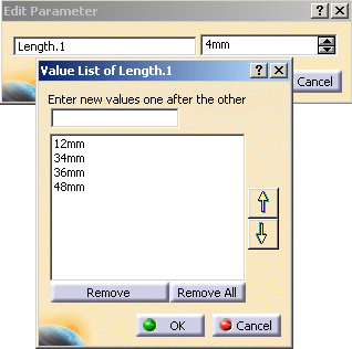
To assign multiple values to a parameter, select Multiple values at parameter creation and enter the values one by one to specify the value list.
Switching between Simple and Multiple Values After Creating a Parameter
It is possible to add values to a single value parameter after creating it. To do so, use one of the 2 methods described below:
First Method |
|
|
|
|
|
|
 |
Second Method |
|
|
|
|
 |
There are two ways to proceed:
Or
Only user parameters can be deleted (the Material parameter cannot be deleted).
Displaying parameters in the f(x) dialog box
The parameter list displayed in the Formulas Editor depends on the selected feature. If you click the document root feature in the specification tree, you display all the document parameters. If you click a given feature in the specification tree, you display only the parameters related to this feature.
Displaying
parameter values in the geometry area
To display parameter values in the geometry area, you must have the Formulas
Editor open. Selecting a parameter from the parameter list will highlight this
parameter in the specification tree and display its value in the geometry area.
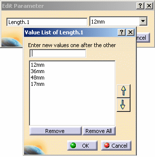
To update the values of a multiple values parameter:
|
 |
Declaring a parameter as constant
Select Properties from the parameter contextual menu. In the Parameter properties tab, check Constant.
Editing or modifying a parameter
There are three ways:
Editing constrained parameters
When a parameter is constrained, a push button is provided opposite the value field of its edition box. This push button represents the relation which constrains the parameters. Clicking this button displays the editor of the relation which constrains the parameter (the formula editor or the rule editor for example).
Adding a comment to a parameter
There are two ways to proceed:
Associating a URL with a parameter
Access the Knowledge Advisor workbench, then click the Comment & URLs icon.
Hiding a parameter from the specification tree
There are two ways to proceed:
Click the
![]() icon in the Knowledge tool bar. Then click
icon in the Knowledge tool bar. Then click
Importing parameters from a VPDM
You can now directly import parameters into the Formula editor from a VPDM.
To reorder parameters, right-click the parameter to be reordered, and select Reorder.... The Reorder dialog box is displayed. In the specification tree, click a parameter below which the parameter to be reordered will be located. Click OK when done.
Specifying a parameter value as a measure
Edit the parameter, then in the value field of the parameter editor, select Measure Between from the contextual menu. The Measure Between dialog box is displayed. You can use this dialog box to measure the distance between two edges for example. Select Between as measure type, then click successively two edges in the geometry area. The distance between both edges is displayed in the Results pane.
Specifying a tolerance (Length or Angle parameter only)
The default tolerance specified in Parameters Tolerance tab of the
|
|
When a formula links two parameters, and if the input parameter has a tolerance, this tolerance will not be propagated to the output parameter. The value is the only information that is taken into account by formulas or rules. |
|
|
To know more about working with parameters please see the About Parameters section. |
For more information on editing tolerances on a sample part, see Computing Mean Dimensions in the Part Design User's Guide.
Specifying lower and upper bounds
Edit the parameter, then in the edition box, right-click the value field and select Add Range.... This capability does not apply to parameters such as booleans or strings.
Specifying an increment/decrement amount
Edit the parameter, then in the edition box, right-click the value field and select Change step.... Select 1mm or click the New one command. In this case, the New step dialog box is displayed and you can enter another step.
Note that:
Specifying the Material parameter value
There are two ways to proceed:
|
|
Select the part you want to apply the
material to, then click the
|
|
|
Edit the material parameter from the specification tree, then enter the new material in the parameter editor. |
Valuating a boolean with a predicate
It is possible to valuate a boolean with a predicate instead of using
operators.
See the example provided in the
KwrPredicate.CATPart file.
Modifying the Part Number of a Part in the Formula Editor
It is possible to modify the part number of a document (CATPart, CATProduct, ...).
Open the document.
Click the
![]() icon in the Knowledge tool bar. Select the Part Number from the parameters
list.
icon in the Knowledge tool bar. Select the Part Number from the parameters
list.
Change the part number in the Edit name or value of the current parameter field.
Note that the part number can also be modified in the Parameters Explorer in Knowledge Advisor.
Creating a Parameters set using a macro
To create a parameters set using a macro, enter the following script:
set mainset =
params.RootParameterSet |
Note that:
|
|
In the Formulas editor, the default step is 1 whatever the unit. |
There are three ways to proceed:
Quickly Accessing Parameters Values in the Formulas Editor
A new field enables you to change a parameter value when creating and especially editing a formula.
|
|
This field is especially useful when you
want to modify the value of a parameter valuated by a formula.
|
Open the KwrPredicate.CATPart file.
Click the
![]() icon in the Knowledge tool bar.
icon in the Knowledge tool bar.
Create 3 parameters of length type with the following values:
|
|
|
Select the Length.3 parameter from the Parameter list and click Add Formula. The Formula Editor is displayed.
Enter the following formula into the editor and click OK when done:
Length.3=Length.2 *Length.1
|
Double-click Length.3 in the specification tree. The Edit Parameter dialog box is displayed.
Click the
![]() icon
located next to the parameter value field. The Formula Editor is displayed.
icon
located next to the parameter value field. The Formula Editor is displayed.
In the Editor, select Length.2 in the Members of All column and set its value to 9mm in its value field.
![]()
Click OK when done. The Length.2 and Length.3 values are updated in the specification tree.
Using the dimensions of a
sketch in a formula
Unless sketch dimensions are declared as constraints, you cannot manipulate
them as parameters in relations. This applies for example to the radius of a
circular sketch or to the width and length of a rectangular sketch.
Editing or modifying a formula
There are four ways to proceed:
Displaying only a formula definition in f(x)
When you click a formula in the specification tree, then click the Formulas icon, the parameter list displays the constrained parameter, the formula activity and the parameters used as input in the formula.
Specifying a measure in a formula or
Edit the parameter, right-click the value field in the parameter edition box, then select Edit formula....
In the formula editor, click Wizard, select the Measures item in the dictionary then select one of the measure functions displayed in the wizard.
Fulfill the function prototype and allow for the required number of arguments. To enter an argument value, position the cursor where the argument is intended to be and capture the feature definition from the specification tree or from the geometry area.
Activating / deactivating a formula
There are three ways to proceed:
Importing parameters and formulas
Click the
![]() icon in the Knowledge tool bar. In the f(x) dialog box, click
Import, then specify the import file path. The import file must be either
a .txt file or a .xls file. The parameters and formulas are applied to the
document. If the imported parameters already exist in the document, the
document is automatically updated by the import process.
icon in the Knowledge tool bar. In the f(x) dialog box, click
Import, then specify the import file path. The import file must be either
a .txt file or a .xls file. The parameters and formulas are applied to the
document. If the imported parameters already exist in the document, the
document is automatically updated by the import process.
There are three ways to delete a formula:
Click
![]() .
From the parameter list of the f(x) dialog box, select the parameter
which is constrained by the formula to be deleted, then click Delete
Formula.
.
From the parameter list of the f(x) dialog box, select the parameter
which is constrained by the formula to be deleted, then click Delete
Formula.
In the specification tree, right-click the formula to be deleted, then select Delete.
Editing the parameter. In the parameter editor, right-click the value field, then select Formula>Delete.
Creating a Design Table from the Document Parameter Values
Click the
![]() icon in the Knowledge tool bar. Check Create a design table with current
parameter values. Select the parameters to insert, then specify the
.xls (Windows) or .txt file where the design table is to be created.
icon in the Knowledge tool bar. Check Create a design table with current
parameter values. Select the parameters to insert, then specify the
.xls (Windows) or .txt file where the design table is to be created.
Creating a Design Table from a pre-existing File
Click the
![]() icon. Check the Create a design table from a pre-existing file.
Specify the file containing the design table data, then create the necessary
associations.
icon. Check the Create a design table from a pre-existing file.
Specify the file containing the design table data, then create the necessary
associations.
There are two ways to proceed:
Or
Adding a Column to a Design Table
To add a column to a design table, open the .txt file in a text editor or the .xls file in Excel, and add a column to the file.
Adding Ranges and Values to a Design Table
It is possible to add ranges and default values to a design table. The ranges will appear between [;], and the default values between <> (see example below).

It is possible to specify a range:
Note that:
In the specification tree, right-click the design table to be deleted, then select Delete.
Making a Query in a Design
Table
The syntax which is authorized in the Filter field of the Design Table dialog
box (Configurations tab) is the same as for Knowledge Advisor checks. You can
type the filtering relation directly in the appropriate field or click
Edit... to access the language dictionary.
An example of a query relation: TangE >10 deg and yE > 10mm
Rearranging Columns in a Design Table
The way columns are arranged in a design table is identical to the way the associations were defined. You can now rearrange the columns without deassociating the parameters and the columns and associating them again just afterwards. To do so, click the Associations tab in the Design Table window, and use the Up and Down arrow buttons.
Selecting the Design Table Editor on Unix
The environment variable CATTermDT enables you to choose the terminal from
which the design tables editor will be started. The editor can be set up by
using the environment variable CATTextEditorDT. xterm is used by default.
This way, you can select the terminal, which can impact the way the editor
behaves. For example, for Japanese users, if vi is started from xterm, vi will
not support kanji whereas if it is started from aixterm (AIX), kanji will be
supported.
Example: export CATTermDT=aixterm
Selecting the Design Table External file from a VPDM
You can now select your design table external file from a VPDM.
About the parameters that cannot be inserted in a design table
Only parameters which are not already constrained by any other relation or
by any other design table can be used to create a design table. If a parameter
is already constrained, it does not appear in the Parameters to insert list in
the design table dialog box.
Tips about selecting the parameters to be inserted in a design table
The Filter Name and Filter Type filters can be used to restrict the display
of a parameter list. If you specify x in the Filter Name field of the Select
parameters to insert dialog box, you will display all the parameters with the
letter x in their name (xA, xB, xC, xD, xE). If you select the Renamed
Parameters from the Filter Type list, you will display all the parameters you
have renamed in the Formulas Editor (yA, xB, xA, yC, xC, yB, yD, xD, yE, xE,
TangE).
Parameters to be inserted can be multiselected. You just have to keep on
pressing the Ctrl key when you select parameters. If you do this, the group of
multiselected parameters will be carried forward onto the Inserted parameters
list in the order in which they are displayed in the initial list.
When the design table is created, the rank of the columns fits the rank of the
parameters in the Inserted parameters list. If you want to have columns ordered
in a given way in the design table, you must insert the parameters one by one.
Tips about the access functions to the design table
In the formula (rule or check) editor, select the Design Table item in the dictionary, the list of the methods that can be applied to a design table is displayed. Select a method, then click F1 to display the associated documentation.
When the active configuration does not fit the set of configurations resulting from a query operation, you get a message prompting you to deactivate the filter (uncheck the filter box) or change your configuration. If neither action is undertaken, your design table takes on a broken status. In the specification tree, a broken or invalid design table is displayed.