 |
This procedure describes how to
create,
move, and reset a shuttle. |
 |
A shuttle is a set of products defined
explicitly by selecting products individually. Shuttles are persistent
and can be stored in your document. Shuttles are identified by name in
the specification tree and by a symbol
 in the
geometry area. in the
geometry area.
When a manikin is selected be a shuttle or a component of a shuttle,
the whole manikin is selected. Individual segments may not be selected. |
 |
|
| |
-
From the Samples directory, open the
Shuttle_sample.CATProduct file.
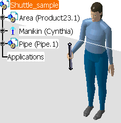
-
Select the Shuttle
 in the Manikin Simulation toolbar and then (while holding down the
Shift key) select the Pipe and the Manikin in the
specification tree.
OR
While holding down the Shift key, select the Pipe and
the Manikin in the specification tree and then select the
Shuttle icon
 in the Manikin Simulation toolbar.
-
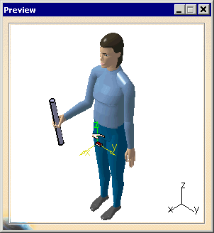
At this time, the following items appear:
- Preview window (the shuttle symbol corresponds to the
to-be-created shuttle axis)
|
|
|
|

|
|
|
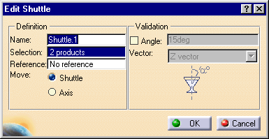
|
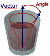
In this dialog box, you can specify a maximum
rotation angle around the absolute axis for the shuttle. This is
very useful in avoiding liquids from spilling out from specific
assemblies such as a gas tank. The shuttle motion is defined and
validated with respect to the angle value defined.
 |
-
In the dialog box, check the Angle option (optional).
The Angle and Vector fields are no longer grayed-out and you may enter
the desired values.
-
Enter a name for your shuttle (optional).
-
OK to finish creating the shuttle.
-
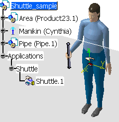
The shuttle, consisting of the pipe and the manikin, is
identified in the specification tree and in the geometry area.
|
 |
|
| |
-
Double-click Shuttle.1 in the specification
tree.
The Edit Shuttle dialog box, the Preview window and the
Manipulation toolbar appear.
Note that, by default, the graphic manipulator is attached to the
shuttle and that the Attach icon in the Manipulation toolbar
is activated.

-
The 3D compass snaps to the shuttle axis.
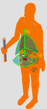
-
The Move shuttle option is activated by default which
means that both the shuttle axis and the geometry move together.
-
Use the 3D compass to move the shuttle to the desired
location.
|
 |
Select the Reset
 in the
Manipulation toolbar. The shuttle will move back to its original
position. in the
Manipulation toolbar. The shuttle will move back to its original
position. |


