Coincidence Constraints

ascenari.gif (1364 bytes) The Coincidence Constraint creates a constraint between a segment and a line or a plane.
  • Line coincidence constraint: the segment end effector meets the vector's direction of the line as if its length was infinite.

  • Plane coincidence constraint: the end effector will place itself on the plane defined by the selected surface on the object. This constraint is a "plane - plane" or "infinite plane" type.


  • 2D Plan Coincidence Constraint will enable you to get a manikin's posture in which a segment will be in coincidence with a plan and also perpendicular to it. This enables a posturing scenario where the manikin has to keep a segment perpendicular and at the same level to a plan. See below,  Editing Default Properties
  1. In the Manikin Constraints toolbar, select Coincidence Constraint.

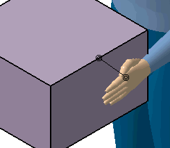
  2. The systems asks you to select a manikin segment. Select the manikin's left hand.

  3. Select a plane or line on the box.

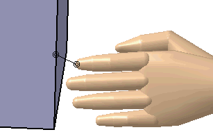
  4. The coincidence constraint is represented by a line with two coincident circles on each end touching the selected segment and the selected line or plane.

By default:

  • The name of the constraint is Constraint X where X is an incremental number.
  • The constraint priority is 1.
  • The constraint is activated.

Editing default properties

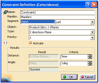
These default properties can be edited in the Constraint Definitions dialog box. To access this dialog box do one of the following:

  • In the 3D view, double-click on the constraint
  • Double-click on the constraint in the specification tree
  • In the 3D view, right-click on the constraint and select Definition... in the contextual menu.


Name: Accept the assigned default name or rename as desired.
Manikin: You may use the manikin originally selected or, in the 3D view, select a new manikin.
Segment: Shows the selected segment. The combo box allows you to select the right or left side of the body for the current constraint. The control is disabled when the current segment is independent of the body side, i.e., the head.  If the arm was selected instead of the hand, if the MoveToPosture changes, the update will not modify the constraint.
Object: The object in the 3D view that shares the constraint with the segment.
Type:
  • The 2 Directions Plain Coincidence creates a constraint between any segments and any plain.  The creation process is exactly as it is for the others constraints.  After updating the constraint, the segment will be perpendicular and at the same to the surface selected for the constraint.

  • The Point on Plane creates a constraint between any segments and any points.

Priority: The priority is in terms of relative weight between the constraints. In a multi-constraint environment, a constraint with priority 1 will be given the most weight, and a constraint with priority 4 will have the least weight. These relative constraint weights will be considered by the software if the following conditions are true:
  • There must exist at least two active constraints on the manikin;
  •  These constraints must be on the same kinematic chains;
  • The system must find no solution to resolve all constraints together.
Passing Criteria: Set a criteria that defines the maximum allowed distance between the segment's end effector and the target object.
Result: Shows the actual distance between the segment's end effector and the target object. The text "Success" or "Failed" is displayed depending whether the distance (length of constraint) is superior or inferior to that amount.

The parameter Angle is available to check if the segment is perpendicular to the plain as it should be.