Using non electrical commands to modify electrical data may lead to inconsistencies in relation to the behavior implemented using electrical commands:
Editing branch points or bundle segment centerlines by double-clicking them is not the recommended method. Use the bundle segment edition command.
As well as editing, modifying, replacing directly
geometrical features created automatically (splits, curves, etc.) or
formulas, those modifications have to be done cautiously.
Moreover, restructuring or reordering those features may lead to
unpredictable results.
Refer to Electrical Harness Installation User's Guide - User Tasks - Working with Branches - Creating/Modifying Segments within a Branch.
In visualization mode, when the part
document is not loaded, an adaptative support is recognized as such if the
ELEC-SUPPORT-RADIUS parameter is published.
To take advantage of this option, you need to publish it manually.
If this option is not selected, or if the parameter is not published, the
support is not seen as adaptative.
Refer to Part Design User's Guide - Advanced Tasks - Using Tools - Publishing Elements.
![]()
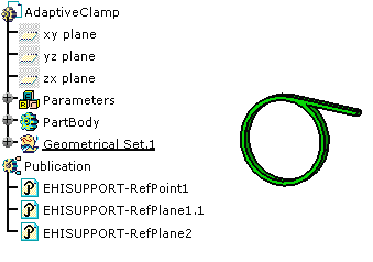
Open the AdaptativeClamp.CATPart document.
![]()
-
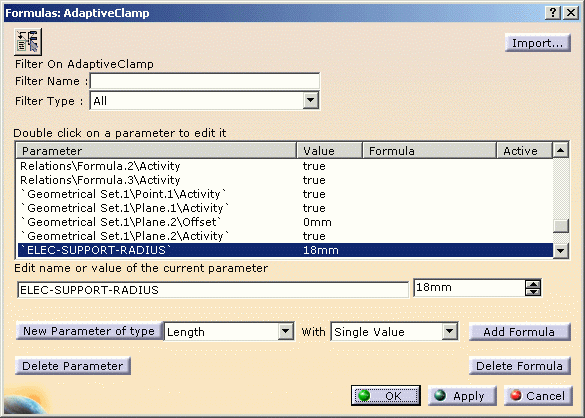
Select the Length as Filter Type and click New Parameter of type.
-
Enter the name for it: ELEC-SUPPORT-RADIUS
and a value: 18mm for exampleNote: the name must strictly be ELEC-SUPPORT-RADIUS. 
-
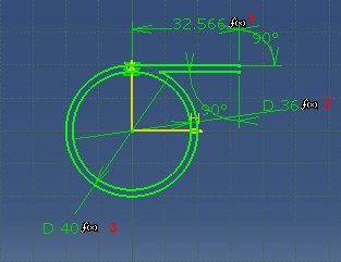
Select the support radius (PartBody\Sketch.1\Radius.50\Radius) and click Add Formula:
-
Enter the formula:
PartBody\Sketch.1\Radius.50\Radius = 'ELEC-SUPPORT-RADIUS' (the radius is equal to the new parameter ELEC-SUPPORT-RADIUS)

-
Click OK to validate the entries made in both dialog boxes.
![]()
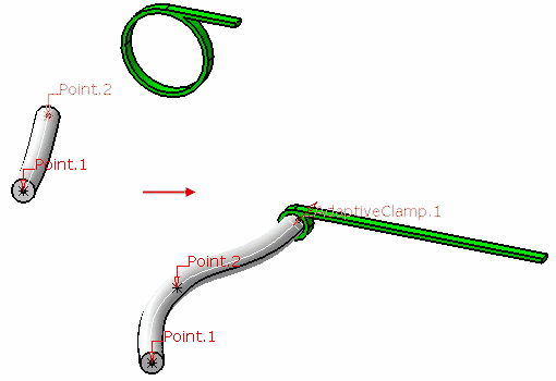
Now, if you route a bundle segment through this support:
A formula will automatically be generated under the root product of the document, if and only if the ELEC-SUPPORT-RADIUS parameter has been detected:
Support radius = Bundle segment diameter * 0.5 - The support will exactly fit the bundle segment diameter. The formulas given above are used to re-compute the support geometry.


