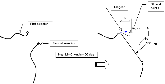
- Angle/Length (Hypotenuse)
- Length1/Angle
- Length1/Length2

The possible chamfer options are displayed in the Sketch tools toolbar. The Trim All Elements option is selected by default.
Six profile mode options are available:
Three dimension mode options are available:
Trimming Both Lines
-
Select the first line and the second line.
The selected lines are highlighted.

The second line is also highlighted, and the two elements are connected by a line representing the chamfer which moves as you move the cursor. This lets you vary the dimensions of the chamfer whose values appear in the Sketch tools toolbar.
-
Click to indicate where to create the chamfer.
The chamfer with both elements trimmed is created.
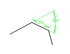
Provided the Dimensional Constraint option command is active, the constraints will be created between what we call in the scenarios below the old intersection point and new end points of the lines.
Trimming the First Line
-
Select the first line and the second line.
The chamfer with one element trimmed is created.
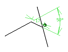
No Trimming
-
Select the first line and the second line.
The chamfer with no element trimmed is created and the original lines are kept.

Trimming Both Lines Until their Intersection
-
Select the first line and the second line.
The chamfer is created and the two lines are trimmed up to the two lines intersection.
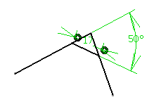
Trimming Both Lines and Creating Construction Lines Until their Intersection
-
Select the first line and the second line.
-
The chamfer is created and the two lines are trimmed.
-
Two new lines are created between the intersection and the trimmed extremity of the lines, and set as construction lines.
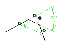
Trimming Both Lines and Creating Construction Lines
-
Select the first line and the second line.
-
The chamfer is created and the two lines are trimmed.
-
Two new lines are created between the previous extremities and the trimmed extremity of the lines, and set as construction lines.
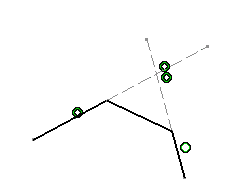
Dimensioning the Edge Intersection Point
You can create several chamfers just by multi-selecting for example, the rectangle endpoints and entering the definition parameters in order to define these chamfers (Sketch tools toolbar). Four chamfers are created at the same time with the same parameter values.
Using the Length1/Length2 Option

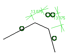
Between Perpendicular Lines

Between Non-Perpendicular Lines

Between Crossing Lines

Between Non-Intersecting Lines
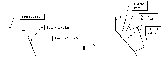
Between Intersecting Curves
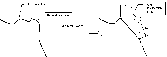
Between Non-Intersecting Curves
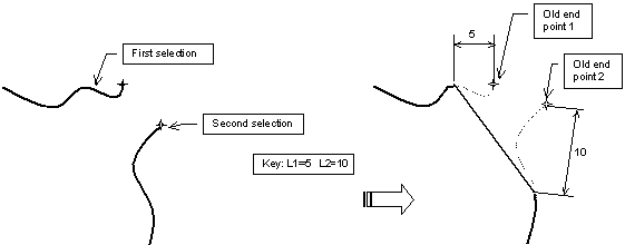
Using the Length1/Angle Option

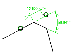
Between Non-Perpendicular Lines

Between Non-Intersecting Curves
