 |
Electrical harness flattening parameters are located in
the Electrical node of the Generative View Style XML file
(available via Tools > Tools > Standard > generativeparameters
category > DefaultGenerativeStyle.XML file).
Customizing these parameters affects the appearance of your drawings.
Note: Generative View Styles only work on Electrical
Harness Flattening data, that is to say after extraction from the 3D
data.
This section deals with the following subjects:
|
 |
All generative view styles apply to views generated in
exact mode. On top of that, some generative view style parameters also
apply when creating other view types (CGR, Approximate and Raster), as
specified for each concerned view dress-up element. |
| |
Bundle Segments
|
 |
| |
| Parameter |
Parameter Name |
Value |
Description |
| GraphicRepresentation |
GraphicRepresentation |
DoubleLine /SingleLine |
Determines the linetype used for
bundle segments.
Default value: DoubleLine |
| |
| AutomaticGeneration > TextTemplate |
Generation |
yes/no |
Specifies whether or not to
generate an associated text template. |
| CatalogName |
character string |
Specifies the name of the
catalog containing text templates. The catalog is the one
identified in the Electrical Drawing Catalog box (Tools
> Options > Equipment & Systems > Electrical Harness
Flattening). If no catalog is specified, the system scans all
catalogs defined in Tools > Options. |
| TextTemplateName |
character string |
Specifies the name of the text
template. |
| |
| AutomaticGeneration > WireAnnotation |
Generation |
yes/no |
Specifies whether or not to
generate wire annotations. |
| Attributes, for example, InstanceName, PartNumber, Diameter |
Integer |
Identifies the order in which
wire attributes are generated. A "0" value means that no annotation
for the selected attribute is generated. |
| |
| AutomaticGeneration > TechnologicalFeatureDimension |
Generation |
yes/no |
Specifies whether or not to
automatically generate dimensions for technological features.
Default value: No |
| |
|
| |
Protective Coverings
|
 |
| |
There are two kinds of protective covering:
Parameters are the same for both kinds of protective covering. |
| |
| Parameter |
Parameter Name |
Value |
Description |
| Tape or Corrugated tube |
GraphicRepresentation |
DoubleLine /SingleLine |
Determines the linetype used for
protective covering.
Default value: DoubleLine |
| Thickness |
yes/no |
Determines whether or not the
customized line type standard is taken into account.
Default value: No |
| |
| 2DdetailOnExtremities |
Generation |
yes/no |
Specifies whether or not to
generate a 2D detail on ends of protective coverings.
Default value: No |
| Coefficient |
integer |
Specifies a coefficient that
sizes the 2D detail according to the layer of protective covering.
Default value: 1.1 |
| CatalogName |
character string |
Specifies the name of the
catalog containing 2D details. The catalog is the one identified
in the Electrical Drawing Catalog box (Tools >
Options > Equipment & Systems > Electrical Harness
Flattening). If no catalog is specified, the system scans all
catalogs defined in Tools > Options. |
| |
| AutomaticGeneration > TextTemplate |
Generation |
yes/no |
Specifies whether or not to
generate an associated text template. |
| CatalogName |
character string |
Specifies the name of the
catalog containing text templates. The catalog is the one
identified in the Electrical Drawing Catalog box (Tools
> Options > Equipment & Systems > Electrical Harness
Flattening). If no catalog is specified, the system scans all
catalogs defined in Tools > Options. |
| TextTemplateName |
character string |
Specifies the name of the text
template. |
| |
| AutomaticGeneration > TechnologicalFeatureDimension |
Generation |
yes/no |
Specifies whether or not to
automatically generate dimensions for technological features.
Default value: No |
| |
|
| |
Devices
|
 |
| |
There are various kinds of device:
- Single insert connectors
- Ground studs
- Terminal strips
- Terminal blocks
- External splices
- Internal splices
- Equipment
- Back shells
Parameters are the same for each of the above devices. |
| |
| Parameter |
Parameter Name |
Value |
Description |
| GraphicReplacement |
Type |
3Dprojection/2D
detail |
Specifies whether to
generate a 3D representation or a 2D detail representing the
device.
Default value: 3D projection. |
| 2DDetailOrientation |
yes/no |
Specifies how to
orient 2D detail.
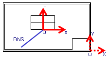
No (default value): 2D detail is oriented with respect to main
drawing view.
Yes: 2D detail is oriented with respect to bundle segment (BNS)
tangency. |
| CatalogName |
character string |
Specifies the name
of the catalog containing the 2D details. The catalog is the one
identified in the Electrical Drawing Catalog box (Tools
> Options > Equipment & Systems > Electrical Harness
Flattening). If no catalog is specified, the system scans all
catalogs defined in Tools > Options. |
| |
2DDetailOrientation=No 
|
2DDetailOrientation=Yes
 |
| AutomaticGeneration >
TextTemplate |
Generation |
yes/no |
Specifies whether or
not to generate an associated text template. |
| CatalogName |
character string |
Specifies the name
of the catalog containing the text templates. The catalog is the
one identified in the Electrical Drawing Catalog box (Tools
> Options > Equipment & Systems > Electrical Harness
Flattening). If no catalog is specified, the system scans all
catalogs defined in Tools > Options. |
| TextTemplateName |
character string |
Specifies the name
of the text template. |
| |
|
| AutomaticGeneration >
WireAnnotation |
Generation |
yes/no |
Specifies whether or
not to generate wire annotations. |
| Attributes, for example, InstanceName, PartNumber,
Diameter |
Integer |
Identifies the order
in which wire attributes are generated. A "0" value means that no
annotation for the selected attribute is generated. |
| |
|
| |
Supports
|
 |
| |
| Parameter |
Parameter Name |
Value |
Description |
| Graphic replacement |
Type |
3Dprojection/2D detail/
3DprojectionAND2Ddetail |
Specifies whether to generate a
3D representation (default value), a 2D detail representing the
support, or both. |
| CatalogName |
character string |
Specifies the name of the
catalog containing the 2D details. The catalog is the one
identified in the Electrical Drawing Catalog box (Tools
> Options > Equipment & Systems > Electrical Harness
Flattening). If no catalog is specified, the system scans all
catalogs defined in Tools > Options. |
| |
|
Graphic replacement> Section of support |
Generation |
yes/no |
Specifies whether or not to
generate an associated support section. |
| Numbering>Use common ditto |
yes/no |
Specifies whether or not
to share a detail. The detail can only be shared if supports have
the same External Reference and same orientation in 3D. |
| Numbering>Prefix on section name |
character string |
Defines prefix to be used
for section details.
Default value: Section |
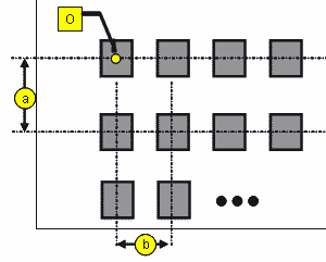
| Layout>Origin position |
length > 0 |
Defines the XY
coordinates of the first detail on the grid.
Default value for X and Y: -400mm |
| Layout>Grid size |
length > 0 |
Defines the spacing
between details in the X and Y directions.
Default value: 40mm |
| Layout>Number of section on X |
Integer |
Defines the number of
details placed along the X direction.
Default value: 10 |

Legend:
O = origin
a = Y step (grid size in Y direction)
b = X step (grid size in X direction)
number of sections along X = 4 in above image |
| |
| AutomaticGeneration > TextTemplate |
Generation |
yes/no |
Specifies whether or not to
generate an associated text template. |
| CatalogName |
character string |
Specifies the name of the
catalog containing the text templates. The catalog is the one
identified in the Electrical Drawing Catalog box (Tools
> Options > Equipment & Systems > Electrical Harness
Flattening). If no catalog is specified, the system scans all
catalogs defined in Tools > Options. |
| TextTemplateName |
character string |
Specifies the name of the text
template. |
| |
|
|
|
Mechanical Parts
|
 |
| |
| Parameter |
Parameter Name |
Value |
Description |
| DashedGreenLine |
LineType |
Integer |
Determines the line type used
for the dashed green line representing the mechanical part. |
| Thickness |
Integer |
Determines the line thickness
used for the dashed green line. |
| |
|
| |
|