Choose a task:
- creating a table,
- editing and modifying a table,
- splitting a table,
- importing a table,
- inserting a view in table.
Creating a table |
|
-
On the Annotations toolbar, click Table
 .
. -
Click a point in the drawing to specify the table position.

Tables cannot be associative. Selecting an element in the drawing does not make the table associative to this element. -
In the Table Editor dialog box that appears, enter the number of columns and rows you want for the table.
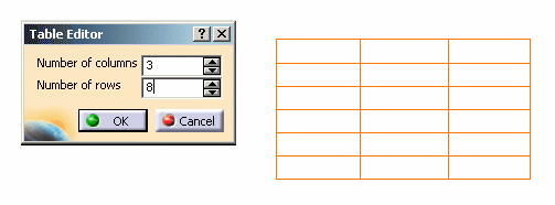

- The line height corresponds to the height of a string.
- The line width corresponds to 5 times the height of a string.
-
Click OK to validate the table creation.
Editing and modifying a table |
|
-
Select the table and drag it to another position.
-
Double-click the table to switch it to edition mode.


You cannot move a table while it is in edition mode. While in edition mode, you can:
-
Select a column by clicking above the column when the symbol
 appears.
 -
Select a line by clicking on the left-hand side of the row when the symbol
 appears.
 -
Leave edition mode by clicking outside the table.
-
-
To access the general contextual menu, right-click the corner of the frame around the table.
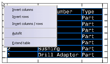
This contextual menu allows you to:
-
invert columns.
-
invert rows.
-
turn rows into columns and columns into rows.
-
fit the text in the cells by automatically defining the optimal cell size.
-
extend the table by adding columns and/or rows to it.
-
-
Choose Invert rows in the contextual menu. Rows are inverted, i.e., the last row becomes the first one, the first row becomes the last one, etc.
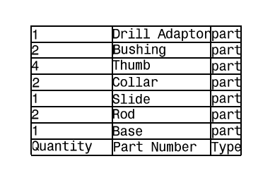
-
Choose Invert Columns in the contextual menu. Columns are inverted.

-
Select Invert Columns / Rows in the contextual menu. Rows and Columns are inverted:

-
Right-click a column or row to access the related contextual menu, which lets you:
-
Insert a column/row.
-
Delete a column/row.
-
Clear the content of a column/row.
-
Modify the size of a column/row by either:
-
setting a new size for the column/row.
-
"autofitting" the size (the optimal cell size is automatically defined in order for text to fit in it).
-
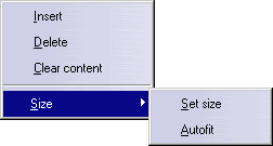

The size of a column or row and the text properties depends on the insertion point in the table. If you insert a column/row: - in the middle of a table, the size and text properties are the same as the preceding column/row.
- at the beginning of the table, the size is the same as the first column/row and the text properties are the same as the current text style.
-
-
Right-click two cells and choose Merge.

You cannot merge a cell that has already been merged. -
Select the new cell formed by the two cells you have merged and choose Unmerge to split them in two cells again.
-
Double-click on the text of a cell. The Text Editor dialog box appears: modify the text and click OK to validate.
-
To choose vertical and horizontal text alignment, use the Anchor point tool
 . Align the text
of a cell on the right using
  .
.
-
Right-click a cell, and select Properties from the contextual menu. The properties available are the same as those available for texts. Refer to Editing Text Properties for more information.
-
On the Font tab, specify a color, red for example, and click OK. The text in the selected cell is now red.

When editing cell properties, note that a number of properties do not apply to the selected cell, but to the table and all its cells. - On the Text tab:
- X and Y position
- (Orientation) Reference
- Orientation
- Blank Background
- On the Graphic tab (Lines and Curves
section):
- Color
- Linetype
- Thickness
- On the Text tab:
Splitting a table |
|
-
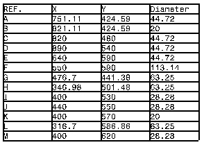
Right-click the table and choose Split Table. The Table Split dialog box appears.
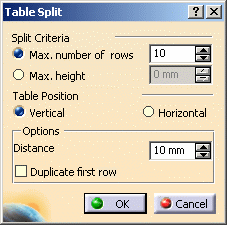
It contains the following options:
-
Max. number of rows: if you want to split the table so that each new table contains a maximum number of rows, select this option and enter the wanted number of rows in the associated field.
-
Max. height: if you want to split the table so that each new table has a maximum height, select this option and enter the wanted height in the associated field.
-
Vertical: check this option to create the new tables one below the other.
-
Horizontal: check this option to position the new tables one next to the other.
-
Distance: indicate the distance you want between each new table.
-
Duplicate first row: check this option if you want to duplicate the first row in each new table.
-
-
Select Max. number of rows, and enter 5 in the corresponding field.
-
Select Vertical.
-
In the Distance field, type 5 mm.
-
Select Duplicate first line.
-
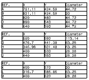
Click OK. The table is split into several tables, according to the criteria you specified.
Importing a table |
|
Values) file, each line corresponds to a line in the table; within a given line, each cell is separated by a specific character that depends on the decimal separator specified in the system options.
This decimal separator determines the character that will be interpreted as the cell separator:
- if the decimal separator is a dot, then the comma (,) is used as the column separator.
- if the decimal separator is a comma, then the semi-column is used as the column separator.
-
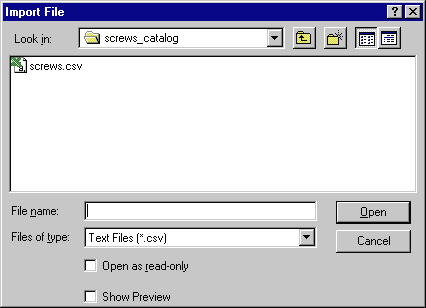
Click Import Table
 and select the table you want to import.
-
Click Open. The table is imported into the drawing.
Inserting a view a in table |
|
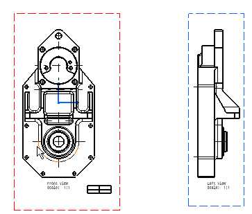
-
Double-click the table to switch it to edition mode.
-
Right-click the cell you want to fill. Select Insert view.
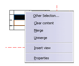

The command "Insert view" is not available with 2D Layout for 3D Design workbench. -
Choose the view you want to insert by clicking the view in the drawing or in the tree.

- You cannot select the view containing the table,
- The view must be in the same drawing.
- If you modify the 3D part and update the drawing, the view in the table will be updated as well.
Choose the Top view:

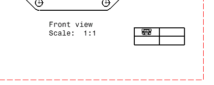
The top view is inserted in the table, and it is resized so as to fit the cell. You can resize the cell if you want to enlarge the view in the table.
![]()