 |
This task shows you how to create geometrical constraints
quickly.
|
 |
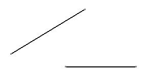
Create two
lines.
|
| |
 |
| |
For the purpose of this scenario, also make sure that the Create
Detected Constraints icon
 is active in the Tools toolbar: this option creates lasting
constraints (if you do not activate this icon, the geometry is only
temporarily constrained, which means that it can subsequently be moved
without being constrained.).
|
 |
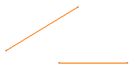
1. Select the geometrical elements
to be constrained to each other. For the purpose of our scenario, select
the two lines you created. |
| |
 |
| |
2. Click the
Geometrical Constraint icon
 from the Geometry Modification toolbar.
 |
| |
 |
| |
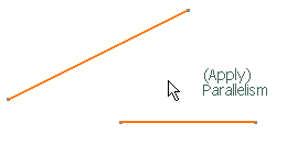
Based on the elements you selected, the software automatically offers
to create a parallelism constraint, as shown at the tip of the cursor. |
| |
 |
| |
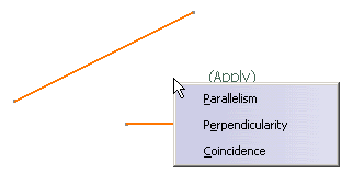
3. At this time, you can
right-click on the drawing, to display a contextual menu offering the other
types of constraints available for the selected elements. |
| |
 |
| |
For the purpose of the scenario, simply click on the drawing to accept
the parallelism constraint. Both lines are now constrained as parallel to
each other. |
| |
 |
| |
4. Modify the position of one of
the lines, by moving one of its end points, for example. |
|
 |
| |
As you can see, the lines are constrained so as to remain parallel to
each other, whatever the new position and/or length you assign to one of
them. |
 |
Even though you set a constraint relation between two elements,
constraints are not necessarily visualized. , go to Tools > Options >
Mechanical Design > Drafting > Geometry tab and select Display
Constraints. (You can also modify the constraint color and/or width.) |
|
 |

![]() is active in the Tools toolbar: this option creates lasting
constraints (if you do not activate this icon, the geometry is only
temporarily constrained, which means that it can subsequently be moved
without being constrained.).
is active in the Tools toolbar: this option creates lasting
constraints (if you do not activate this icon, the geometry is only
temporarily constrained, which means that it can subsequently be moved
without being constrained.).
![]() from the Geometry Modification toolbar.
from the Geometry Modification toolbar.


![]()