For the purpose of this scenario, also make sure that the Create
Detected Constraints
![]() is active in the Tools toolbar: this option creates lasting
constraints (if you do not activate this icon, the constraints you create
are temporary: the geometry is only temporarily constrained, which means
that it can subsequently be moved without being constrained.).
is active in the Tools toolbar: this option creates lasting
constraints (if you do not activate this icon, the constraints you create
are temporary: the geometry is only temporarily constrained, which means
that it can subsequently be moved without being constrained.).


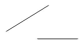
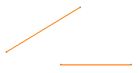
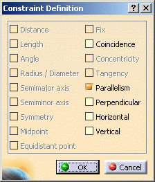
3. Select the Parallelism option to specify that the selected lines should be parallel.


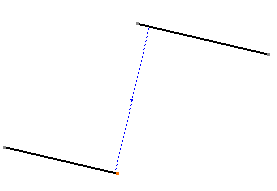
5. Modify the position of one of the lines, by moving one of its end points, for example.

- It is impossible to create constraints between 2D and generated elements via the Constraint Definition dialog box. In the Constraint Definition dialog box, you can only create constraints between similar elements. In other words, you can create constraints either between 2D elements, or between generated elements, but not between a mix of these.
- Even though you set a constraint relation between two elements, constraints are not necessarily visualized. , go to Tools > Options > Mechanical Design > Drafting > Geometry tab and select Display Constraints. (You can also modify the constraint color and/or width.)
![]()