-
Right-click the sheet in the specification tree (press F3 to display it).
-
Select Edit > Properties.
-
The Sheet tab contains a number of properties:
General properties

Enter a meaningful name for the sheet.
Scale
Specify the scale (i.e. the scaling factor) which applies to all views in the sheet.
Format properties

This list contains the format names defined by the administrator in the Standards Editor. For more details, see Sheet Format Definition in the Administration Tasks chapter.
You may also create your own user-defined formats, defined locally for a given drawing. To create your own format, proceed as follows:
- Type a name for the format in the Format field.

The name of the newly created format must be different from those in the user-defined and in the standard lists of formats. If not, a warning message is displayed to inform you the format name you chose is not valid. - Use the tab key to access the Width and Height fields and set their values.
Display the frame representing the format of the sheet.
Width
Width of the selected format. This field is available for user-defined formats only.
Height
Height of the selected format. This field is available for user-defined formats only.
Orientation
Orientation of the selected format. Available only if the selected format allows you to modify the orientation type. For more information, refer to Sheet Format Definition.
Projection Method

First angle standard
Select this option if you want all views in the sheet to be created using the first angle standard.
The first angle standard is an orthographic representation comprising
the arrangement, around the principal view of an object, of some of all of
the other five views of that object. With reference to the principal view,
the other views are arranged as follows:
- the view from above is placed underneath
- the view from below is placed above
- the view from the left is placed on the right
- the view from the rear is placed on the left or on the right, as
convenient.
(Ref. No. ISO 10209-2:1993)
Third angle standard
Select this option if you want all views in the sheet to be created using the third angle standard.
The third angle standard is an orthographic representation comprising
the arrangement, around the principal view of an object, of some of all of
the other five views of that object. With reference to the principal view,
the other views are arranged as follows:
- the view from above is placed above
- the view from below is placed underneath
- the view from the left is placed on the left
- the view from the rear is placed on the left or on the right, as
convenient.
(Ref. No. ISO 10209-2:1993)
Generative Views Positioning Mode

Part bounding box center
Select this option if you want generative views to be positioned according to the center of the 3D bounding box. This mode ensures that the center of the 3D bounding box remains at a fixed position on the sheet, when views are updated.
Part 3D axis
Select this option if you want generative views to be positioned according to the 3D axis system. This mode ensures that the projection of the 3D axis remains at a fixed position on the sheet, when views are updated (even if the center of gravity of the 3D geometry has changed).
Example

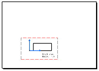
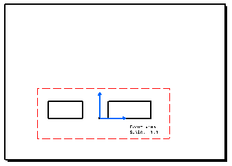
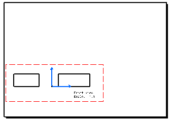
- If Part center of gravity is selected: the center of gravity of the 3D geometry remains at a fixed position on the sheet after the update.

- If Part 3D axis is selected: the projection of the 3D axis remains at a fixed position on the sheet after the update.

Print area

Check this box to specify that only a specific area of the sheet should be printed. Doing this will activate the associated fields so that you can define the print area.
Note that on top of checking this box, you must select Document area option as the Print area in the Print dialog box in order for the print area to be printed. If you do not select the Document area option, the whole document will be printed. Refer to Printing Sheets for more information.
X
Specify the X coordinate of the lower left-hand corner of the print area.
Y
Specify the Y coordinate of the lower left-hand corner of the print area.
Width
Specify the width of the print area.
Height
Specify the height of the print area.
apply a format
Select a format if you want to define the print area using the width and height specified for that format.
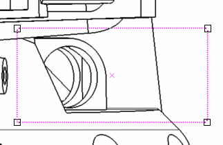
Use the manipulators at the corners of the box to re-dimension the print area.
Drag the dashed box or the central X cross to re-position the print area.

-
Change the sheet properties as wanted, and then click OK to validate.