-
Right-click the front view and select Edit > Properties.
-
Click the View tab. You can notice that a number of options are disabled, as they apply to generative views only.
-
Choose your options.
Visualization and behavior

- Display View Frame: shows/hides the view frame,
- Lock View: locks the view so that it cannot be modified anymore.
- Visual Clipping: lets you reframe a view so as to display only part of it. Refer to Reframing a View for more information.
Scale and Orientation
![]()
- Angle: defines the angle between the view and the sheet,
- Scale: defines the scale of the view.
- =: displays the decimal value with respect to the fraction. This field is read-only.
|
|
|
View Name

-
Click OK to validate and exit the Properties dialog box.
Properties Available on Generative Views
In the case of generative views (Generative Drafting workbench), a number of additional properties will be available. The properties described below apply to generative views only, and will be active in a Generative Drafting context.
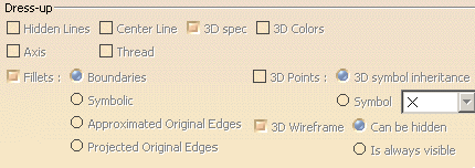
Dress-up
Specifies the dress-up elements that should be displayed in the view:
- Hidden Lines: generates hidden lines.
- Center Line: generates center lines.
- 3D Spec: specifies whether, in an assembly, the properties
assigned to given parts (also called components) will be applied in the
view.
The following 3D specifications may be defined for components in the Product Structure workbench:
- The component will, or will not, be cut when projected in section views (Do not cut in section views).
- The component will, or will not, be projected in views (Do not use when projecting).
- The component will, or will not, be represented with hidden lines (Represented with hidden lines).
For more information, refer to Modifying Component Properties in the Product Structure User's Guide.
- 3D Colors: specifies that the colors of a part should be automatically generated onto the views.
- Axis: generates axis lines.
- Thread: generates threads.
- Fillets: generates fillets. You can choose to view Boundaries, Symbolic, Approximated Original Edges, Projected Original Edges:
Boundaries
Thin lines, representing the mathematical limits of the fillets.Boundaries will not be projected if they correspond to two faces which are continuous in curvature. They will be projected only if they correspond to a smooth edge which is situated between two faces whose curvature radii vary.
This mode will be used automatically to represent a connection between two faces which are not joined by a fillet, no matter what option you select.
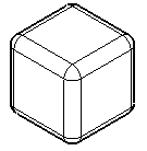
Symbolic
Original edges, projected in a direction that is normal to each corresponding surface.
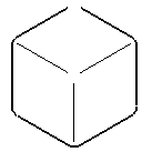
Approximated Original Edges
Original edges, at the intersection of the two surfaces joined by the fillet.
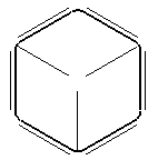
Projected Original Edges
Original edges, projected on fillet surfaces in the direction of the view projection.
This projection mode is equivalent to the CATIA V4 fillet projection mode.
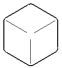
- Dimensions on such fillets are not associative.
- Such fillets cannot inherit 3D colors. Likewise, when using generative view styles, such fillets cannot inherit the 3DInheritance view dress-up parameters (defined in Tools > Standard > generativeparameters > *.XML file, Drafting > ViewDressup > 3DInheritance).
- Always have in mind that those fillets representations are only a symbolical preview of the 3D.
- 3D Points: projects points from 3D (no construction elements). You can choose from the following options:
3D symbol inheritance: keeps the symbol from the 3D.
Symbol: displays the symbol you choose from the drop-down list.
Additional customization is available with Generative View Style parameters.
- 3D Wireframe: displays both the wireframe and the geometry on generated views. You can choose whether projected 3D wireframe can be hidden or is always visible:
Can be hidden: with this option selected, 3D wireframe geometry will follow standard removal of hidden lines.
Is always visible: with this option selected, 3D wireframe geometry will not follow standard removal of hidden lines and will always be visible.Whichever option you choose, note that linear elements will not be projected as points when they are perpendicular to the projection plane, in section views and projection views.
The section cut is a particular case: after the cut operation, it considers a wireframe as a series of points. To visualize them, check the two options Project 3D wireframe and Project 3D points are selected (in Tools > Options > Mechanical Design > View tab).

Generation Mode
- Only generate parts larger than: specifies that you only want to generate parts which are larger than the size indicated (in millimeters) in the appropriate field.
- Enable occlusion culling: saves memory when generating exact views from an assembly (or a part or product) which is loaded in Visualization mode (i.e. when the Work with the cache system option is active). This will load only the parts which will be seen in the resulting view (instead of loading all of them, which is the case by default), which optimizes memory consumption and CPU usage.
- View generation mode: lets you change how the view is
generated. A short description of the various view generation modes is
provided below. For a detailed description (including the advantages and
restrictions pertaining to each mode), refer to View Creation > About the
View Generation Modes. To a lesser extent, you may also refer to
Customizing Settings > View.
- Exact view: turns the view into a exact view (the geometry becomes available).
- CGR: turns the view into a CGR view (only the external appearance of the component is used and displayed; the geometry is not available).
- Approximate: turns the view into an approximate view. Although approximate views are not as high in precision and quality as exact views, this generation mode dramatically reduces memory consumption. Performances may also be improved, depending on how you fine-tune precision (click the Options button). Therefore, the approximate mode is particularly well-adapted to sophisticated products or assemblies involving large amounts of data.
- Raster: turns the view into an image view. You can
configure a number of options such as the level of detail or the type
of image to generate (shading, shading with edges, etc.) .
Generative view style

- The Generative view style area shows the generative view style which is applied to the view.
- If you have modified the values of the properties defined in the selected generative view style by editing some dress-up properties, for example, you can use the Reset to style values button to reset these values to the original style values. (To let you know when properties have been changed compared to the original generative style, an asterisk is displayed in front of them.)
![]()