|
|
This scenario does only apply to Interactive Drafting workbench when dealing with purely Interactive views and Interactive items issued from Generative views, i.e. Sketcher geometry. |
-
Click Thread Dimension
 in the Dimensioning toolbar (Dimensions
sub-toolbar).
 -
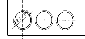
In the front view, select the thread to be dimensioned. The thread diameter dimension appears.

-
Click Thread Dimension
 again.
 -
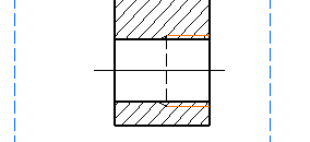
In the section view, select the two lines representing the thread to be dimensioned.

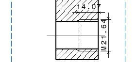
Two thread dimensions appear, representing the thread diameter as well as the thread depth.

More on Thread Dimensions |
|
|
When adding a thread dimension an editable "M" prefix is added by default. For more information on editing symbol icons, refer to Editing Dimension Texts Properties in the Common functionalities section. |
|
|
Both dimensions and prefixes of the views shown here below are editable. That is to say you can customize the prefix and the dimension data will update as you modify the geometry. However you can not edit any item generated from a 3D object at least you first isolate the generative view. By default, generated dimensions are in green. | ||||
|
|
When updating a pure Interactive thread dimension the prefix i.e. "M" remains unchanged. However if you update a generative view the prefix will also be updated and therefore displaying the prefix used in the 3D object. | ||||
|
![]()

