|

|
Available in Composites Design (CPD) and Composites Engineering Design (CPE),
in a CATPart context.
The core sampling is performed on the CATPart or on a
selection of plies groups.
The result can be stored in the CAPTPart.
You will:
- define a core sampling point (Location/Direction),
- select the elements on which you will perform the core sampling
(Filters),
- click
Apply to visualize the result in the dialog box,
- click OK to save the result in the CATPart,
-
export the result from the specification tree, if necessary.
Available in DMU Composites Review (CPR), in a CATProduct
context.
The core sampling is performed on the whole CATProduct or on a selection of CATParts under the
CATProduct.
However the core sampling result will not be stored in the CATProduct: OK is
disabled.
You will:
- define a core sampling point (Location/Direction),
- select the elements on which you will perform the core sampling
(Filters),
- click
Apply to visualize the result in the dialog box,
-
export the result from the dialog box, if necessary,
- click Cancel to exit the dialog box without saving the
result in the CATProduct.
You can perform several core samplings with different core sampling
points. |

|
-
Click Core Sampling
 . .
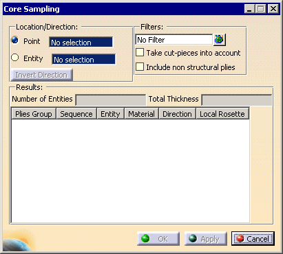
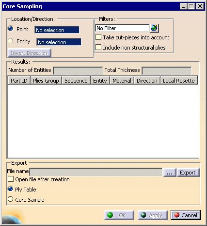
The Core Sampling dialog box is displayed:
In Composites Design (CPD) and Composites Engineering Design (CPE):
In DMU Composites Review (CPR):
-
Define the
Location/Direction of the core sampling by a
core sampling point:

- you can either select an existing point:
click click
Entity and select the entity where you want to
indicate a core sampling point.
Then pick this entity again where you want the core
sampling point to be.
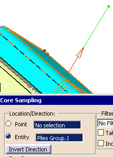
This entity can be:
- a plies group,
- a ply,
- a cut-piece,
- a tape,
- a surface.
|
 |
The core sampling point must lie on the surface:
- With the option Point, you must select a point that
lies on the surface.
- With the option Entity, if the indicated point does
not lie on the surface, its projection on the surface is used.
In both cases, a core sample feature will be created. However if you
indicate a point,
this point will not be modified if you modify the surface (only its 3D
coordinates are stored, not its position on the surface). |
 |
In Composites Design (CPD) and Composites Engineering Design (CPE), the option
Point offers you the
possibility to create a point with a contextual menu.
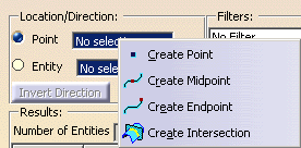
In DMU Composites Review (CPR), this contextual menu is not available. The core sampling point
must already exist. |
-
If necessary, you can modify the location/direction:
-
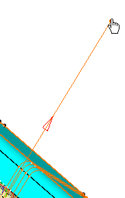
using the manipulators that appear in the 3D geometry. You can drag them
both sides.
-
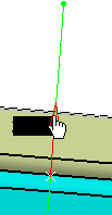
using the direction arrow: it shows you in which direction the plies
will be taken into account.
Click the arrow in the graphic area, or click
Invert Direction in the
dialog box to invert the direction.
|
-
Filters lets you define the selection of entities on which
the core sampling will be performed.

|
In Composites Design (CPD) and Composites Engineering Design (CPE):
- by default, the whole CATPart is selected.
- click
 to select plies groups.
- if you select an element under a plies group, the plies group is
automatically selected.
In DMU Composites Review (CPR):
- by default, the whole CATProduct is selected.
- click
 to select CATParts under the CATProduct.
- if you select an element under a CATPart, the CATPart is
automatically selected.
If there are any:
- select the Take cut-pieces into account
check-box to take them into
account.
- select the Include non structural plies
check box to take them into account.
|
-
Click Apply to analyze all the plies on each
side of the point.
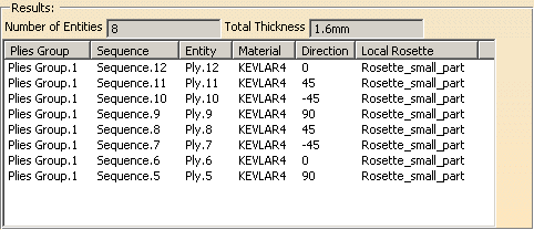
The dialog box is updated and the number of plies as well as the total
thickness is displayed
(we have resized the dialog box):
In Composites Design (CPD) and Composites Engineering Design (CPE),
the table looks like this:
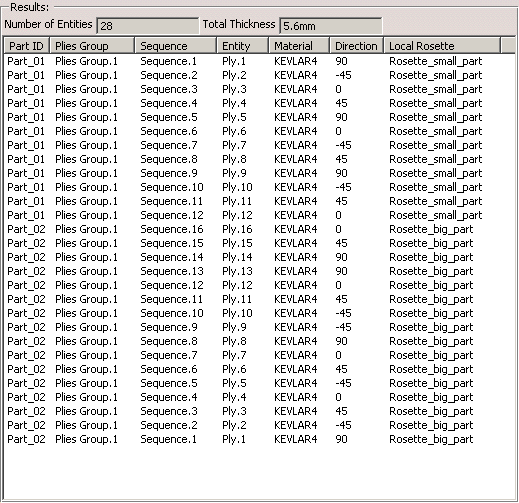
In DMU Composites Review (CPR), the table has one more
column, for the Part ID:
Note that:
-
the plies appear in their real order,
-
if any, cut-pieces that intersect each other are displayed in the list.

|
-
In DMU Composites Review (CPR), you can
export
the result of the core sampling:

Click ... to enter the path and the name of the export file.
Select the Open file after creation check box if you want to do
so.
Select the option corresponding to the format required for the export file.
Click Export.
Ply Table:
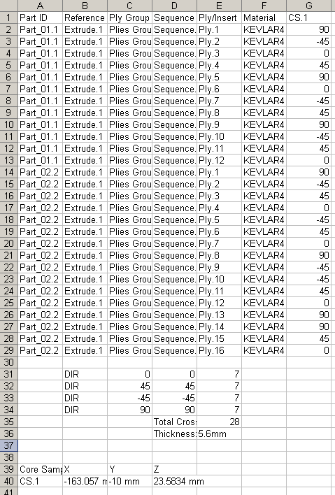
The plies with multiple intersections, if any, are listed at the end,
the number of multiple intersections is given for each ply concerned.
Core Sample:
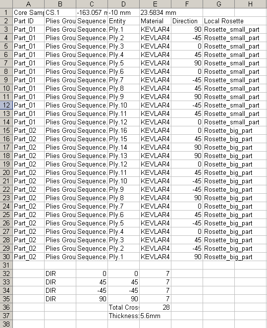
The plies are listed in the order they have been processed, which
makes the multiple intersections more visible, if any.
Click Cancel to exit the dialog box.
In the Composites Design (CPD) and Composites Engineering Design (CPE):
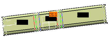
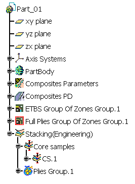
Click OK to create the core sample and exit the dialog
box.
-
In Composites Design (CPD) and Composites Engineering Design (CPE),
once the core sampling is created, you can
export it from the specification
tree:

If the Core samples node contains several Core samples elements, they are
all listed in the xls file.
The Core Samples dialog box is displayed:
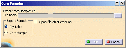
Click ... to enter the path and the name of the export file.
Select the Open file after creation check box if you want to do
so.
Select the option corresponding to the format required for the export file.
Click OK.
Ply Table:
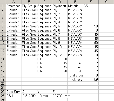
All plies are listed by their name.
The plies with multiple intersections,
if any, are listed at the end,
the number of multiple intersections is given for each ply concerned.
Core Sample:
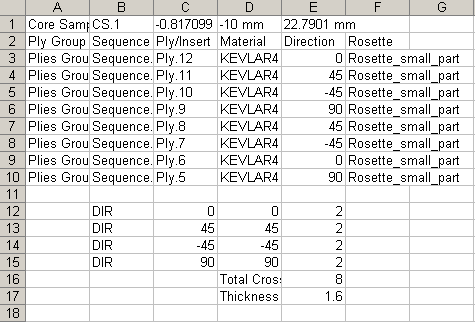
The plies are listed in the order they have been processed, which
makes the multiple intersections more visible, if any.
|