Creating Octree 2D Mesh Parts

This task shows you how to create a 2D mesh using triangle elements.

This command is available both in the Generative Structural Analysis workbench and in the Advanced Meshing Tools workbench. Options available in the Octree triangle mesher are different depending on the products you have installed:


Generative Part Structural Analysis (GPS) or FEM Solid (FMD)

Top

In this configuration, the dialog box allowing you to define Octree 2D mesh parts contains only two tabs either in the Generative Structural Analysis workbench or in the Advanced Meshing Tools workbench.

  1. Click Octree Triangle Mesher (in the Model Manager toolbar for the Generative Structural Analysis workbench or the Meshing Methods toolbar for the Advanced Meshing Tools workbench).

  2. Select the 2D geometry.

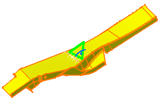
    A symbol appears on the geometry and the OCTREE Triangle Mesh dialog box appears.

  3. Modify the desired options. In this particular case, keep the default options.

  4. Click OK.

    The OCTREE Triangle Mesh.2 mesh parts appears in the specification tree. Note that now the corresponding 2D Property is missing. For more details on how to add this property, refer to Generative Structural Analysis User's Guide - User Tasks - Model Manager - Creating 2D Property.
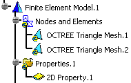
    You can change the physical property of the 2D mesh element you have just created using the Changing Type contextual menu.

  • 2D mesh can be deleted and/or added to parts manually.

  • To visualize the mesh in the Generative Structural Analysis workbench, use the Mesh Visualization contextual menu.
    The mesh is automatically displayed in the Advanced Meshing Tools workbench.
 

FEM Surface (FMS)

Top


In this configuration, the dialog box allowing you to define Octree 2D mesh parts contains four tabs either in the Generative Structural Analysis workbench or in the Advanced Meshing Tools workbench.
  1. Click Octree Triangle Mesher (in the Model Manager toolbar for the Generative Structural Analysis workbench or the Meshing Methods toolbar for the Advanced Meshing Tools workbench).

  2. Select the geometry to be meshed.

    To do this, select either the surface in the specification tree or select the part.
    A symbol appears on the geometry:

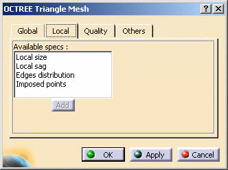
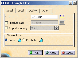
     The OCTREE Triangle Mesh dialog box appears.

    • Global tab:

       
      • Size: lets you specify the size of the mesh elements.
      • Absolute sag: maximal gap between the mesh and the geometry.
      • Proportional sag: is the ratio between the local absolute sag and the local mesh edge length.

        Proportional sag value= (local Absolute sag value) / (local mesh edge length value)

        • Note that Absolute sag and Proportional sag could modify the local mesh edge length value.

        • You can use both Absolute sag and Proportional sag, the most constraining of the two values will be used.

      • Element type: lets you choose the type of element you want (Linear or Parabolic).
        To know more about the Element Type you have to choose in the OCTREE Triangle Mesh dialog box, refer to Linear Triangle and Parabolic Triangle in the Finite Element Reference Guide.
    • Local tab:
      You can also add local meshing parameters such as sag, size or distribution to the part.
      To do this, select the desired Available specs and then click the Add button. A different dialog box opens according to the Available specs you have selected.
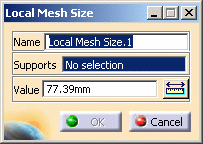
      • Local size: you can modify the Name, Support and Value.
      • Local sag: you can modify the Name, Support and Value.
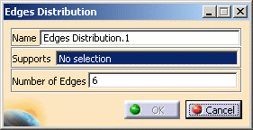
      • Edges distribution: lets you distribute local nodes on edges.
        To do this:
        • Select the Edges distribution option and click Add. The Edges Distribution dialog box appears.
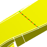
        • Select the edge on which you want to assign nodes (Supports) as well as the Number of Edges to be created.
          The Edges Distribution.1 feature now appears in the specification tree.
        • Click OK in the Local Mesh Distribution dialog box.
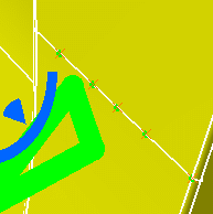
          In this particular case, 7 nodes are generated, i.e. 6 edges will be generated after the meshing.

      • Imposed points: lets you select the points that will be taken into account when meshing.

        In this case, the points you have to select must have been created via Shape Design or Part Design.
        Only points on curve or points on surface are supported. The points support must be a member of the meshed geometry.

        To do this:

        • Select the Local imposed points option and click Add.
          The Imposed Points dialog box appears.
        • Select from the specification tree (under Open Body feature) the points (Supports) you will impose for OCTREE triangle mesh generation.
        • Click OK in the Imposed Points dialog box.

          To edit the local mesh distribution that has just been created, you need to double-click the Local Nodes Distribution object in the specification tree and modify the desired options from the Local Mesh Distribution dialog box that appears.

    • Quality tab:
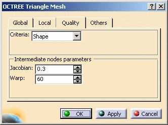
      • Criteria: lets you choose a criterion (Shape, Skewness or Strech) to optimize the mesh quality.
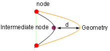
      • Intermediate nodes parameters: only available if you have chosen a Parabolic element type in the Global tab. This option lets you choose the position of parabolic triangle intermediate nodes (Jacobian or Warp).
        The distance (d) between the geometry and the intermediate node is function of Jacobian and Warp values.

    For more details about mesh quality analysis, refer to Analyzing Element Quality in the Advanced Meshing Tools User's Guide.

    • Others tab:
      • Details simplification: lets you remove small mesh.
        • Geometry size limit: lets you specify the maximum size of the elements to be ignored by the mesher (before the meshing).

          If all the edges of a surface are smaller than the Geometry size limit value, this surface will be ignored by the mesher.

        • Mesh edges suppression: removes small edges (after the meshing).

          Without Mesh edge suppression:

          With Mesh edge suppression:

          It may happen that Mesh edge suppression involve constraints violation.

      • Global interior size: not available in Octree triangle mesh.
      • Min. size for sag specs: lets you specify the minimum size of the mesh refining due to sags specifications.
      • Max. number of attempts: lets you impose a maximum number of attempts, if several attempts are needed to succeed in meshing, in the case of a complex geometry.
  3. Select the desired parameters in the OCTREE Tetrahedron Mesh dialog box.

  4. Click Apply.

    The Computation Status dialog box appears.

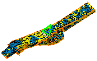
    The OCTREE Triangle mesh is generated on the part.

  5. Click OK.

To edit the Octree triangle mesh, double-click the OCTREE Triangle Mesh.1 object in the specification tree.
The OCTREE Triangle Mesh dialog box reappears.