 |
This command is only available with the Automotive BiW
Templates product.
To access this command in the Part Design workbench, Automotive
Class A, Automotive BiW Templates or FreeStyle Optimizer licenses are
required. |
 |
This task shows how to create a 3D support. It is composed
of three regular grid of lines, generally set on the three main planes of
the part, that aggregates 3 selectable work on supports.
It allows you to create reference points on the fly on each support,
whenever you need a reference point to create other geometric elements. You
will no longer have to explicitly select the support element.
It also allows you to create sub-elements of the grid on the fly (points,
edges). These features do not appear either in the specification tree or
in the 3D geometry but are aggregated under the feature using them. |
 |
Open the
WorkOnSupport1.CATPart document. |

|
-
Click Work on Support 3D
 . .
| The Work On Support 3D dialog box appears. |
| Part Design default configurations do not provide
this icon in the standard toolbar. If you wish to access it, simply
use the Customize capability to add this icon to the toolbar of your
choice. Otherwise, select the Tools > Work on Support 3D
item from the menu bar. |
 |
| |
 |
- Each of three grid lines has one default primary spacing of
100mm for each direction. The three directions of the main axis
system define the grids directions.
You can edit the spacing values by clicking on the spacing tag to
edit and modify them.
Note that you can modify these values at creation, not at edition,
and that there can only be one value per grid.
Grids are used both as an input to create geometry as well as
visual help.
- You can also modify the name of the labels of the main
directions by clicking on the direction tag.
- Labels' directions and primary spacing are defined in
Tools > Options > Shape > Generative Shape Design.
Refer to the Customizing section for further information.
|
-
Choose the Labels position:
-
Full Screen: labels are displayed all
around the screen
-
Bottom/Left: labels are displayed on the bottom left of the
screen
-
None:
no label is displayed
|
-
Define the Support Type:
-
Reference: the 3D support is created according to the main
axis system. There can be only one reference 3D work on support.
-
Local: a local axis system must be specified. There can
be as many local 3D works on support as desired.
|
-
Click OK in the dialog box.
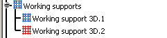
| The element (identified as Working support 3D.xxx) is added to
the specification tree under the Working supports node as shown
below. |
 |
-
Select Top View
 from the View toolbar.
| The active work on support is visualized and labels
are displayed on each straight line. |
| |
 |
|
|
-
The work on
support must be parallel to one of the three planes to be
visualized. As a consequence, the active 3D work on support may be
seen independently in each view of the same document.
-
If you move
the compass, the 3D work on support is no longer parallel to the
screen.
-
There can
only be one active 3D work on support at the same time.
|
|
|
When the local axis system is
modified, all related features are updated. |
|
| |
Setting a work on support as current
|
|
|
By default, the last created working support is displayed
in red in the specification tree.
Select the Set As Current/Set As Not Current
contextual item on the working support features or click Working
Supports Activity
 to define which is the default current support
that will be automatically selected when entering a command that requires a
working support.
to define which is the default current support
that will be automatically selected when entering a command that requires a
working support.
You can also set the axis system as not current to deactivate the three
planes and define the reference support as the current support. |
| |
|
| |
Snapping to a point
|
| |
Click Snap to point
 to snap the point being created onto the nearest intersection point on the
grid.
to snap the point being created onto the nearest intersection point on the
grid. |
| |
Switching
the featurization to lines or planes
|
| |
Click the Grid Featurization Switch
 to create either featurized lines or featurized planes on the grid lines.
Featurized planes are created normal to the current grid.
to create either featurized lines or featurized planes on the grid lines.
Featurized planes are created normal to the current grid. |
|
|
| |
|
|
- Use the Get Features on Support
contextual item on the working support features to
retrieve the features created from a single or a
multi-selection works on support. As a result, the retrieved
features are selected in the current editor and highlighted in
the specification tree, therefore allowing you to use them more
easily.
-
Activate
Work on Support Selection State
 in the User Selection Filter toolbar to be able to select
sub-elements from the grid.
in the User Selection Filter toolbar to be able to select
sub-elements from the grid.
For further information, refer to the Selecting Using A Filter
chapter in the CATIA Infrastructure User's Guide.
- Once you choose to work on the 3D support, you can directly
click onto the support to create points. This capability is
available with commands such as
point, line, spline, polyline,
and most commands where you need to select points as inputs.
| The created points using a
support are aggregated under the parent command that
created them and put in no show in the specification tree. |
 |
- The children that appear under any
feature may not follow the same order as their order of
creation.
- Each 3D working support can be edited, updated, or deleted
just as any other feature.
|
| |
- In case you are working in a CATProduct
environment, and providing there are several parts, you can
only see the 3D working support whose part is active. If the
product is active, 3D working supports cannot be applied.
- The Work on Support 3D command
can now be used along with the Measure Between command.
Refer Using the Measure Between Command With a 3D Support
chapter for further information.
|
|
|

|