Note that you need to put the desired geometrical set in current to be able to perform the corresponding scenario.
For instance, if you choose the Center and radius type, you are not able to select an axis. May you want to select an axis, choose another type in the combo list.
Defining the plane type
Center and radius
-
Click Circle
 .
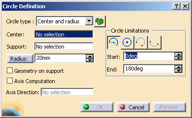
.The Circle Definition dialog box appears. -
Select the Center and radius circle type.
-
Select a point as circle Center.
-
Select the Support plane or surface where the circle is to be created.
-
Enter a Radius value.
Depending on the active Circle Limitations icon, the corresponding circle or circular arc is displayed.
For a circular arc, you can specify the Start and End angles of the arc.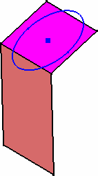

If a support surface is selected, the circle lies on the plane tangent to the surface at the selected point.
Start and End angles can be specified by entering values or by using the graphic manipulators.
-
Click OK to create the circle or circular arc.
The circle (identified as Circle.xxx) is added to the specification tree.
Center and point
-
Click Circle
 .
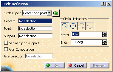
.The Circle Definition dialog box appears. -
Select the Center and point circle type.
-
Select a point as Center.
-
Select a Point where the circle is to be created.
-
Select the Support plane or surface where the circle is to be created.
The circle, which center is the first selected point and passing through the second point or the projection of this second point on the plane tangent to the surface at the first point, is previewed.
Depending on the active Circle Limitations icon, the corresponding circle or circular arc is displayed.
For a circular arc, you can specify the Start and End angles of the arc.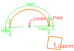
-
Click OK to create the circle or circular arc.
The circle (identified as Circle.xxx) is added to the specification tree.
Two points and radius
-
Click Circle
 .
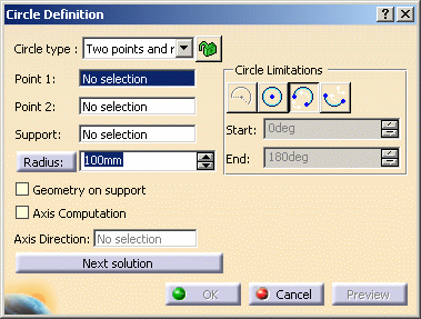
.The Circle Definition dialog box appears. -
Select the Two points and radius circle type.
-
Select two points on a surface or in the same plane.
-
Select the Support plane or surface.
-
Enter a Radius value.
The circle, passing through the first selected point and the second point or the projection of this second point on the plane tangent to the surface at the first point, is previewed.
Depending on the active Circle Limitations icon, the corresponding circle or circular arc is displayed.
For a circular arc, you can specify the trimmed or complementary arc using the two selected points as end points.
You can use the Next Solution button, to display the alternative arc.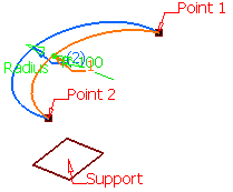
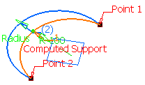
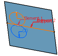
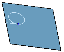
With a plane as Support With a direction as Support (the computed plane is shown in blue) -
Click OK to create the circle or circular arc.
The circle (identified as Circle.xxx) is added to the specification tree.
Three points
-
Click Circle
 .
.The Circle Definition dialog box appears. -
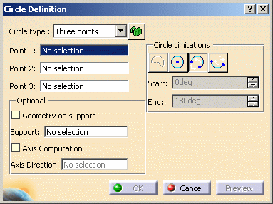
Select the Three points circle type.
-
Select three points where the circle is to be created.
Depending on the active Circle Limitations icon, the corresponding circle or circular arc is displayed.
For a circular arc, you can specify the trimmed or complementary arc using the two of the selected points as end points.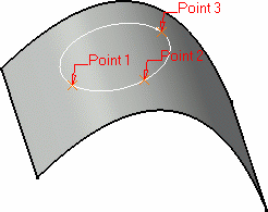
-
Click OK to create the circle or circular arc.
The circle (identified as Circle.xxx) is added to the specification tree.
Center and axis
-
Click Circle
 .
.The Circle Definition dialog box appears. -
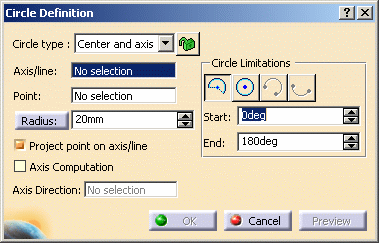
Select the Center and axis circle type.
-
Select the axis/line.
It can be any linear curve. -
Select a point.
-
Enter a Radius value.
-
Set the Project point on axis/line option:
-
checked (with projection): the circle is centered on the reference point and projected onto the input axis/line and lies in the plane normal to the axis/line passing through the reference point. The line will be extended to get the projection if required.
-
unchecked (without projection): the circle is centered on the reference point and lies in the plane normal to the axis/line passing through the reference point.
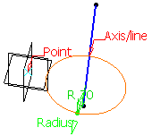
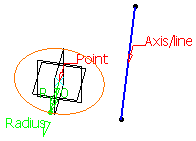
With projection Without projection -
-
Click OK to create the circle or circular arc.
The circle (identified as Circle.xxx) is added to the specification tree.
Bitangent and radius
-
Click Circle
 .
.The Circle Definition dialog box appears. -
Select the Bitangent and radius circle type.
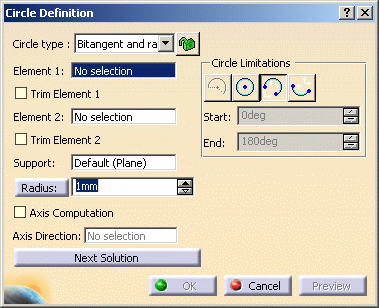
-
Select two Elements (point or curve) to which the circle is to be tangent.
-
Select a Support surface.

If one of the selected inputs is a planar curve, then the Support is set to Default (Plane).
If an explicit Support needs to be defined, a contextual menu is available to clear the selection in order to select the desired support.
This automatic support definition saves you from performing useless selections. -
Enter a Radius value.
-
Click OK to create the circle or circular arc.
The circle (identified as Circle.xxx) is added to the specification tree.
Bitangent and point
-
Click Circle
 .
.The Circle Definition dialog box appears. -
Select the Bitangent and point circle type.
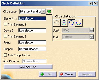
-
Select a point or a curve to which the circle is to be tangent.
-
Select a Curve and a Point on this curve.
The point will be projected onto the curve. -
Select a Support plane or planar surface.
-
Click OK to create the circle or circular arc.
The circle (identified as Circle.xxx) is added to the specification tree.
Tritangent
-
Click Circle
 .
.The Circle Definition dialog box appears. -
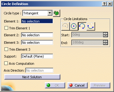
Select the Tritangent circle type.
-
Select three Elements to which the circle is to be tangent.
-
Select a Support planar surface.

If one of the selected inputs is a planar curve, then the Support is set to Default (Plane).
If an explicit Support needs to be defined, a contextual menu is available to clear the selection in order to select the desired support.
This automatic support definition saves you from performing useless selections.Several solutions may be possible, so select the arc of circle that you wish to create.
Depending on the active Circle Limitations icon, the corresponding circle or circular arc is displayed. The first and third elements define where the relimitation ends.
For a circular arc, you can specify the trimmed or complementary arc using the two tangent points as end points.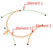
You can check Trim Element 1 and Trim Element 3 to trim the first element or the third element, or both elements.
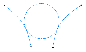
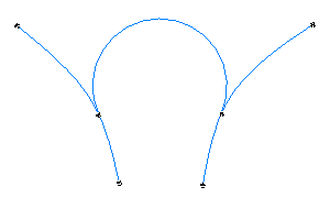
Here is an example with Element 3 trimmed.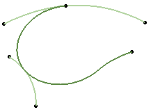

- Trim Element 1 and Trim Element 3 are only available with the Trimmed circle limitation.
- You cannot create a tritangent circle if an input point lies on an input wire. We advise you to use the bi-tangent and point circle type.
-
Click OK to create the circle or circular arc.
The circle (identified as Circle.xxx) is added to the specification tree.
Center and tangent
-
Click Circle
 .
.The Circle Definition dialog box appears. -
Select the Center and tangent circle type.
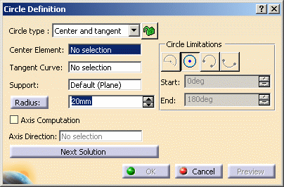
The circle center will be located either on the center curve or point and will be tangent to the tangent curve.
There are two ways to create a center and tangent circle:Center curve and radius:
-
Select a curve as the Center Element.
-
Select a Tangent Curve.
-
Enter a Radius value.

Line tangent to curve definition:
-
Select a point as the Center Element.
-
Select a Tangent Curve.
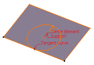

- If one of the selected inputs is a planar curve, then the
Support is set to Default (Plane).
If an explicit Support needs to be defined, a contextual menu is available to clear the selection in order to select the desired support.
This automatic support definition saves you from performing useless selections. - Note that only full circles can be created.
-
-
Click OK to create the circle or circular arc.
The circle (identified as Circle.xxx) is added to the specification tree.
Using the Diameter/Radius options
This option is available with the Center and radius, Two point and radius, Bi-tangent and radius, Center and tangent, and Center and axis circle types.
Note that the value does not change when switching from Radius to Diameter and vice-versa.
Using the Axis Computation option
-
You can select the Axis computation check box to automatically create axes while creating or modifying a circle. Once the option is checked, the Axis direction field is enabled.
-
If you do not select a direction, an axis normal to the circle will be created.
-
If you select a direction, two more axes features will be created: an axis aligned with the reference direction and an axis normal to the reference direction.
In the specification tree, the axes are aggregated under the Circle feature. You can edit their directions but cannot modify them.
If the datum mode is active, the axes are not aggregated under the Circle features, but one ore three datum lines are created.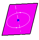
Axis normal to the circle 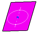
Axis aligned with the reference direction (yz plane) 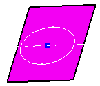
Axis normal to the reference direction (yz plane) -
If you check Geometry on Support and the selected support is not planar, then the Axis Computation is not possible.
You can check Geometry on Support if you want the circle to be projected onto a support surface.
In this case just select a support surface.
This option is available with the Center and radius, Center and point, Two point and radius, and Three points circle types.When several solutions are possible, click Next Solution to move to another arc of circle, or directly select the arc you want in the 3D geometry.
A circle may have several points as center if the selected element is made of various circle arcs with different centers.
Parameters can be edited in the 3D geometry. For more information, refer to Editing Parameters.
You can isolate a circle in order to cut the links it has with the geometry used to create it. To do so, use the Isolate contextual command. For more information, refer to Isolating Geometric Elements.
![]()
