Open the Axis1.CATPart document.
-
Click Axis
 .
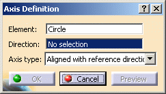
.The Axis Definition dialog box appears. -
Select an Element where to create the axis.
This element can be:
Circle
-
Select the direction (here we chose the yz plane), when not normal to the surface.
-
Select the axis type:
- Aligned with reference direction
- Normal to reference direction
- Normal to circle
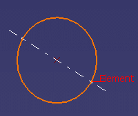
Aligned with reference direction 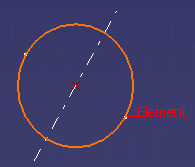
Normal to reference direction 
Normal to circle
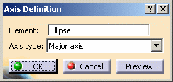
Ellipse
-
Select the axis type:
- Major axis
- Minor axis
- Normal to ellipse
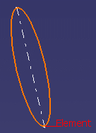
Major axis 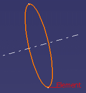
Minor axis 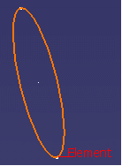
Normal to ellipse
Oblong Curve
-
Select the axis type:
- Major axis
- Minor axis
- Normal to oblong
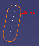
Major axis 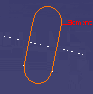
Minor axis 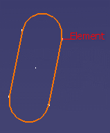
Normal to oblong
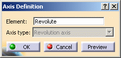
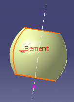
Revolution Surface
The revolution surface's axis is used, therefore the axis type combo list is disabled.
-
Click OK to create the axis.
The element (identified as Axis.xxx) is added to the specification tree.
The axis can be displayed in the 3D geometry, either infinite or limited to the geometry block of the input element. This option is to be parameterized in Tools > Options > Shape > Generative Shape Design > General.
To have further information, refer to the General Settings chapter in the Customizing section.
![]()
