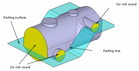
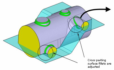
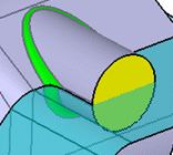
In case you do not want to fillet the whole part, just select the faces to be filleted and optionally select what we call "functional faces": these faces identify the edges you do not want to fillet nor round.
Using Autofillet is therefore a good way of drastically reducing the time spent on filleting.
Rounding Versus Filleting
When rounding or filleting, the application replaces sharp edges by blending circular surfaces. The term "Rounding" applies to convex sharp edges. Rounding removes material from the part. Conversely, the term "filleting" is appropriate for non-convex sharp edges. Filleting adds material to the part. This terminological distinction is to be made when running AutoFillet since it computes fillets and rounds altogether while complying with mechanical specifications, meaning that very often, the rounding radius value differs from the filleting radius value.
Scenario
This section provides a scenario showing you how to use the capability thru a representative example of autofilleting, then discusses the following topics:
-
Click Automatic Filleting
 in the Advanced Dress-up Features toolbar
 .
.
The Automatic Filleting Definition dialog box appears.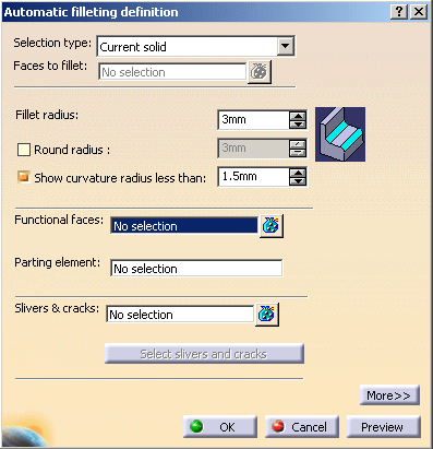
-
Optionally, click More to expand the dialog box and display images helping you define your specifications.

-
The Selection Type field lets you specify a computation mode among two possible ones:
- Current solid: the whole current solid is filleted. This is the default mode.
- Faces selection: the edges around the faces selected are filleted.
Help images reflect the computation mode you select. For the purpose of our scenario, keep Current solid.
-
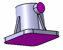
The Functional Surfaces field lists the faces you do not want to fillet. Select both yellow faces as the faces which edges you do not want to fillet. The selected faces turn purple, indicating that they will not be filleted.
-
Keep 3mm as the radius value you want to assign to edges, whatever they are: convex or not.
-
Filleting applies to sharp edges that are not convex. This operation adds material to the part. Rounding applies to sharp edges that are convex. This operation removes material from the part. Because of mechanical reasons, a distinction is to be made between filleting and rounding. The command lets you assign distinct radius values to the different edge types.
By default, Round Radius is disabled. This means that if you modify the radius value, the round value is automatically modified and displays the same value as the radius value.
For the purpose of our scenario, select this option to apply a radius value different from 3 mm to rounds. Enter 2mm.
If this option is disabled, its value is half the smallest value. For example, if the fillet radius value is 5 and the round corner value is 4, then the value used is 2. -
Select Show curvature less than: field to ensure that the application displays the fillets and rounds whose radius value is less than the smaller radius value you entered. In our example, in case the application generates fillets or rounds whose radius value is less than 2mm, a warning message will therefore be issued.
-
Check OK to confirm.
A new dialog box appears, indicating the operation progress. In case you want to interrupt the operation, just click Cancel.
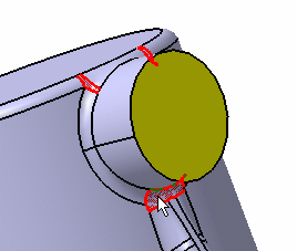
Because the application detects fillets or rounds whose radius value is less than 2mm, the following warning message is issued:
-
To show the fillets and rounds, select the warning message from the Warnings window.
The fillets and rounds are displayed in red in the geometry area:
-
Click Close to close the Warnings window.
The operation is complete. All the edges except for edges surrounding both functional surfaces are filleted. A new feature identified as AutoFillet.XXX is added to the specification tree. Compared with manual filleting, using AutoFillet is also a way of considerably reducing the number of features in the specification tree.
Non-filleted Areas
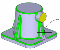
For different reasons, there might be cases where the system is not able to deal with all the edges to be modified. When this happens, the system does not stop at the first error encountered but computes as many rounds and fillets as possible and leaves the remaining edges untouched (see the figure below) so that you just have to finish the job manually.
 |
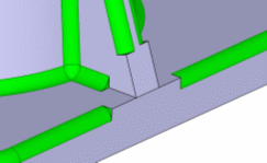 |
| Unchanged remaining edges: you need to use the traditional Fillet capabilities |
The application issues a warning message to help you identify non-filleted edges.
Slivers and Cracks
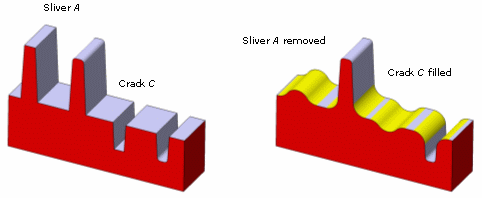
A sliver is an unwanted thin wall which should be smoothed and partially removed by the automatic filleting operation. A thin wall that is not rounded is not processed by the Autofillet capability unless you select it as a sliver. For an example, see sliver A in the figure below.
A crack is an unwanted slot which should be smoothed and partially filled by the automatic filleting operation. Similarly, a slot that is not rounded is not processed by the automatic filleting algorithm unless you select it as a crack. For an example, see crack C in the figure below.
|
|
 |
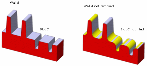
If you do not select them as slivers or cracks, thin walls and thin slots are rounded and filleted by Autofillet, as illustrated below. The resulting height and depth of walls and slots are slightly decreased. Furthermore, the resulting curvature radius is less than the given round or fillet radius because of small thicknesses.
 |
Managing Curvatures
Two capabilities are provided to help you obtain the best possible result:
- The Preview capability provides a way of anticipating problems.
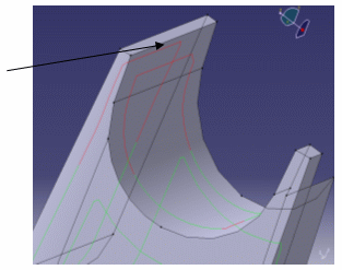
- The Select slivers and cracks capability is available after clicking Preview. It automatically adds the slivers and cracks to the selection. Faces corresponding to slivers and cracks are displayed in green.
Using Preview
|
The Preview capability allows you to see the different areas where problems arise and therefore help you select the slivers and cracks to get the best possible result. Using Preview, you can see
|
 |
Using Select Slivers and Cracks
|
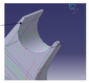
Clicking on Select slivers and cracks automatically adds the slivers and cracks which are not yet selected and which are mandatory to run the automatic fillet correctly. Then you just need to click Preview again to obtain the next result: the lines are green, the problem is solved.
|
 |
Limitations
-
Dedicated to casting rounds and fillets, Autofillet has been designed for robustness purposes rather than shape and curvature precision. Surfaces resulting from automatic filleting may not be as precise as those obtained using the traditional Fillet capabilities. Consequently, you should create design rounds and fillets on the part before performing an automatic filleting.
-
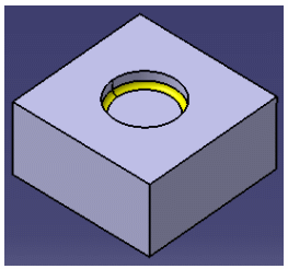
The bounding edges of a smooth skin (a set of faces sharing smooth edges) are sharp. Autofillet instantly aborts if the input body contains any sharp edge whose bounded faces belong to the same smooth skin.
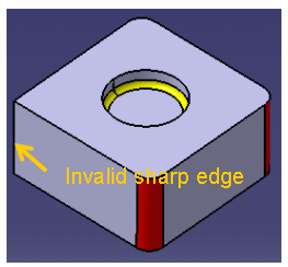
Incorrect input
Correct input
-
To be able to edit or update the geometry produced by AutoFillet, a Cast and Forged Part Optimizer license is required. Otherwise, the only solution for being able to work on parts containing AutoFillet features is to deactivate those features until edit or update operations can be achieved in a CATIA session with a Cast and Forged Part Optimizer license.
