Model
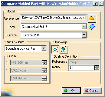
Path and name of the CATPart you are going to compare with the CATPart that
is already in your workbench.
Click
![]() icon to browse your directories to the location of the CATPart.
icon to browse your directories to the location of the CATPart.
Element in the reference file that you wish to import. Use the combo list to select it.
- If the CATPart selected contains a PartBody, i.e. a solid, this PartBody is proposed by default.
- If there is no valid PartBody available, the first non-empty Geometrical set is proposed.
If you wish to import a set of faces, click
![]() (for importing closed
solids) so that the icon for importing a set of faces is displayed,
(for importing closed
solids) so that the icon for importing a set of faces is displayed,
![]() ,
,
then choose your file.
Surface that you wish to use for the computation and is only displayed
when you have a choice of surfaces to use in the body.
The surface proposed
by default is the last surface in the Geometrical set,
because it should be
the most complete surface, i.e. the most susceptible to be closed.
Axis System
Defines the origin of the Molded Part, and also the initial axis system.
The Origin position (X,Y,Z) is defined via one of the following menu
options:
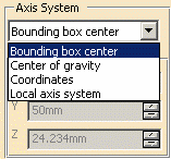
- Bounding box center: the origin is the center of the virtual bounding box around the part.
- Center of gravity: the origin is the center of gravity of the model.
- Coordinates: you can enter an origin and the system will be parallel to the main axis system.
- Local axis system: the origin is that of the axis system that is defined in the model you are importing.
The Axis system is generated according to the option which has been selected:
- with Local axis system: with the axis system planes of the model imported,
- with the other options: with the standard main planes.
Shrinkage
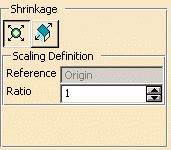
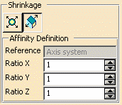
Plastic shrinkage can be allowed for either by:
- Scaling
 :
the default Scaling ratio proposed is 1. You can modify this value.
The reference point for Scaling is the origin of the Axis System defined just before.
This point cannot be modified in this frame. - or Affinity
 which is defined by giving 3 axis ratios. The default Affinity ratio
proposed is 1 along the 3 axes.
You can modify the 3 ratios. The Axis system of the Affinity (Origin, Plane XY, Axis X) is the one defined just before.
This axis system cannot be modified in this frame.
Comparison
Click OK in the Compare Molded Part dialog box to display the
Comparison dialog box.
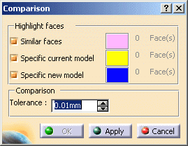
- Similar faces displays the faces that are identical in both models,
- Specific current model displays the faces that are specific to the original model,
- Specific new model displays the faces that are specific to the new model (the one that was selected in the Compare Molded Parts dialog box).
The color slabs give the color that the corresponding faces are displayed
in and allow you to differentiate the faces on screen.
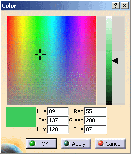
You can change the
colors by double clicking on the slabs and then selecting the colors you
want to use.
Tolerance gives the distance within which two faces are considered to be identical.