 |
This task explains how to modify the radius of
fillets found with the Search Fillets command. The Search Fillets
command and the Fillet Radius Reduction
command are two steps of one tool that helps
you find fillets and
reconstruct them to reduce the processing time on large models.
However, not
all cases are detected nor can be reconstructed.
- Faces in the NoShow are not dealt with.
- Fillets with variable radius are not dealt with.
- Faces smaller that 0.1 mm are not dealt with.
- Once you have clearly identified strip of fillets to process, we
recommend that you join those fillets.
- We recommend that you use the Target radius option.
- The result of the reconstruction depends directly of the quality of
the faces to process.
|
 |
- You recommend that you perform a fillet search, although it is not
mandatory.
- Only rarely can all the surfaces retrieved with the Search
Fillets command be used directly to recreate fillets.
Be sure that you process areas with consistent fillets.
|
 |
-
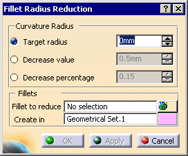
Click Fillet Radius Reduction
 in the Modify Fillet Radius toolbar.
The Fillet Radius Reduction
dialog box is displayed.

-
Specify the
curvature radius value
to be reached:

- Select Target radius (recommended option) and enter the value
to be reached
- or select Decrease value and enter an
absolute value by which the current value of each fillet will be
decreased.
- or select Decrease percentage and enter
the percentage of reduction of the current fillet.
|
-
If necessary, display the User Selection Filter
toolbar (View>Toolbars>User Selection Filter).
Click
 to select surfaces or
 to select faces.
-
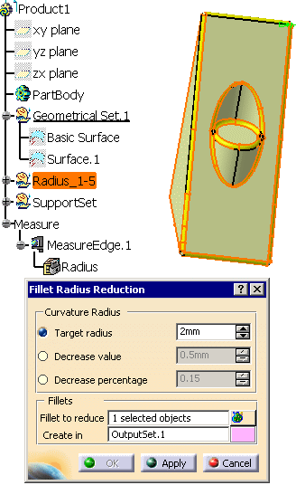
Select the
fillet to reduce, either by selecting surfaces
or faces or a Geometrical Set.
Multi-selection is available.
-
Create in proposes you a Geometrical Set in
which the output surfaces will be created.
You can edit its name and change its color (double-click the color patch
to start the color editor).
If the Geometrical Set does not yet exist, it will be created.

-
Click Apply to compute and display the new surfaces in the
3D viewer and in the specification tree.
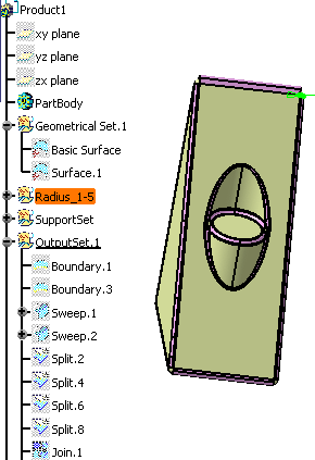
In feature mode, the specification tree will look like this:

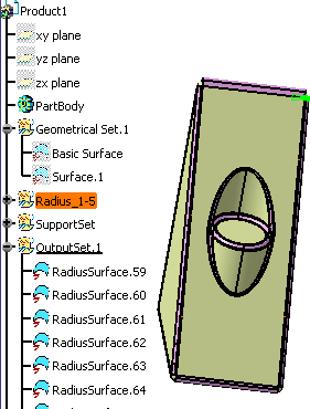
In datum mode it will look like this:

The feature mode is useful when you need to modify
the model.
However, if the quantity of data is an issue, you can work in datum mode, to avoid creating
too many data.
|
|
 |