More information about the parameters is available in the Transfer an Element Parameters chapter.
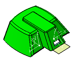
In the example below, we have extruded the lower edge of the
large Slider/Lifter face (in yellow) to build a surface (Extrude.1).
![]()
If, for any reason, you want to move this face to the Cavity
area, you will lose the structure of Extrude.1.
The action Transfer an Element moves the face to another area
without destroying the structure of any element built on it.
-
Click Transfer an Element
 in the Pulling Direction toolbar
and select Cavity as the destination.
in the Pulling Direction toolbar
and select Cavity as the destination.
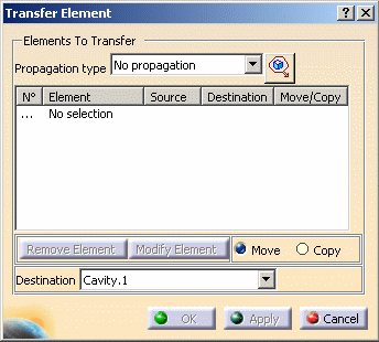
-
Pick the yellow face. It is transferred to the cavity area.
![]()
-
Click OK.
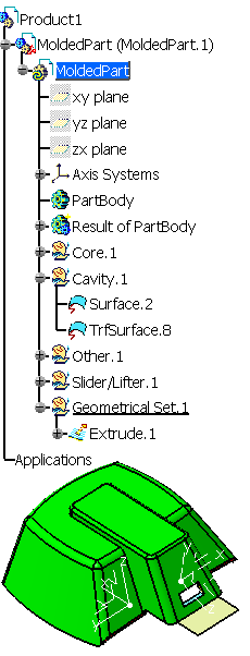
If no features point to the initial surface, the initial surface is deleted.
A progress bar indicates the advancement of the computation.
![]()