-
Click the TestUDF type and the Sequential
Combination behavior icon ( )
to create a combination of behaviors.
-
Double-click SequentialCombination in the Behaviors
View and double-click TestUDF in the Behaviors tab. The Sequential
Combination is displayed in the Behaviors tab.
-
Double-click the SequentialCombination combination in the
Behaviors tab to edit it. The Sequential Combination editor is displayed.
-
In the Name field of the opening dialog box,
enter Instantiate UDF and click OK to validate.
-
Select the Instantiate UDF combination in the Behaviors
tree and click the Sequential Combination icon ( ).
Sequential Combination is displayed in the Behaviors tab.
-
In the Name field of the opening dialog box,
enter Retrieve Part and click OK to validate.
 |
At this stage of the scenario, the Behaviors tree
looks like the one opposite. |
 |
-
Click the Retrieve Part combination and click
the Bind Object behavior icon ( ).
).
-
Double-click the Bind Object node. The Bind Object editor
is displayed.
|
|

|
".." indicates that the bind must be
performed on the upper level. In the current context, you go up 4
levels to reach the root product and go down one level to access
the PartResult. |
|
|
-
Click the Retrieve Part combination and click
the Bind Reference behavior icon ( ).
BindReference is displayed in the Behaviors tab.
-
Double-click the BindReference node. The Bind Reference
editor is displayed.
-
Click the Retrieve Part combination and click
the Bind Part behavior icon ( ).
BindPart is displayed in the Behaviors tab.
-
Double-click the BindPart node. The BindPart editor is
displayed.
|
|
|
|
 |
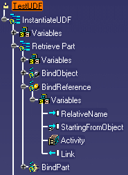
At this stage of the scenario, the behaviors tree
looks like the one opposite. |
 |
-
Select the
Instantiate UDF combination in the Behaviors tab and click the
Sequential Combination icon ( ).
SequentialCombination is displayed in the Behaviors tab.
-
Double-click SequentialCombination. The Sequential
Combination editor is displayed.
-
In the Name field of the opening dialog box,
enter Retrieve Publications and click OK to
validate.
-
Click the Retrieve Publications combination
and click the Bind Object behavior icon ( ).
).
-
Double-click the Bind Object node. The Bind Object editor
is displayed.
-
Click the Retrieve Publications combination
and click the Bind Publication Behavior icon ( ).
BindPublication is displayed in the Behaviors tab.
-
Double-click the BindPublication node. The Bind
Publication editor is displayed.
-
Click the Retrieve Publications combination
and click the External Reference Behavior icon ( ).
CreateExternalReference is displayed in the Behaviors tab.
-
Double-click the CreateExternalReference node. The Create
External Reference editor is displayed.
|
|
|
|
|
|
|
|
 |
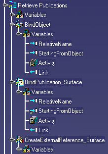
At this stage of the scenario, the behaviors tree
looks like the one opposite. |
 |
-
Click the Retrieve Publications combination
and click the Bind Publication Behavior icon ( ).
BindPublication is displayed in the Behaviors tab.
-
Double-click the BindPublication node. The Bind
Publication editor is displayed.
-
Click the Retrieve Publications combination
and click the External Reference Behavior icon ( ).
CreateExternalReference is displayed in the Behaviors tab.
-
Double-click the CreateExternalReference node. The Create
External Reference editor is displayed.
|
|
|
|
|
|
|
|
 |
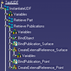
At this stage of the scenario, the behaviors tree
looks like the one opposite. |
 |
-
Select the Instantiate UDF combination in
the Behaviors tab and click the Sequential Combination icon ( ).
Sequential Combination is displayed in the Behaviors tab.
-
Double-click the SequentialCombination. The Sequential
Combination editor is displayed.
-
In the Name field of the opening dialog box,
enter Retrieve UDF and click OK to validate.
-
Click the Retrieve UDF combination and click
the Load Document Behavior icon ( ).
LoadDocument is displayed in the Behaviors tab.
-
Double-click the LoadDocument node. The Load Document
editor is displayed.
-
Click the Retrieve UDF combination and click
the Bind User Feature
Behavior icon ( ).
BindUserFeature is displayed in the Behaviors tab.
-
Double-click the BindUserFeature node. The Bind User
Feature editor is displayed.
|
|
|
|
|
|
 |
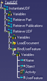
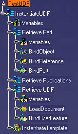
At this stage of the scenario, the behaviors tree
looks like the one opposite. |
 |
-
Click the InstantiateUDF combination and click
the Instantiate Template Behavior icon ( ).
InstantiateTemplate is displayed in the Behaviors tab.
-
Double-click the InstantiateTemplate node. The
Instantiate Template editor is displayed.
|
|
|
|
|
|
|
|
 |
At this stage of the scenario, your workbench is
similar to the graphic opposite.
|
 |
The UDF is inserted into the product.
![]()